- Selling Product
- Radio Communications and Radar Similarities
- Amazon Kuiper LEO SATCOM Flat Antenna Array
Selling Product
Many companies, regardless of their size, have a misunderstanding of product design process and cycle.
It starts with an assumption that having a new technology, it can produce a selling product. Although that could become to be reality for some, it is not a generally true and many become victim to that misunderstanding.
The fallacy of building a product based on internal technical know-how and engineering is that the Business Requirements would be solely derived from what can be achieved internally, rather than what the market really needs.
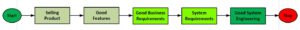
Any selling product has fine features. These features are captured in the Business Requirements with someone with vision, understanding of market, as well as technical know-how.
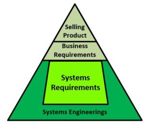
The disrupter product pyramid is built from Top to Bottom, which maybe counter intuitive.
If your product is not selling as it should or expected to be. You don’t have the appropriate product, which implies the Product Business Requirements are not what it should be. If there is no appropriate Business Requirements, then there is no amount of Engineering that can satisfy the market.
That is where product vision comes to be critical to yield sell or not selling product.
Work with ORTENGA to capture an appropriate Business and System Requirements for your technology.
Inquiry: info@ortenga.net
Posted on May 23, 2021
Radio Communications and Radar Similarities
Radio Communications and Radar have been two distinct technologies in their own industries. However, in the past decade, the advancement of technologies both in Academia as well as implementations and integrations of radio and processor in to more devices from handheld to terminal based have led to some interesting overlaps between these two industries. This blog will briefly walk through the similarities and overlap of implementations.
Perhaps the most difficult problem of Terrestrial radio communications is fading mitigation. Fading is not only function of frequency but also of the environment or terrain. This makes it new problem to solve, every time, the radio is supposed to operate at different frequency or environment.
Radars typically operate in open environments and the small echo from their targets arrives at receiver directly. Any multipath echo is too small in amplitude to be resolved with meaningful information. On the other hand, the radar target aspects impact the radio signal similar to what environment do to radio communication signal. Target scintillation is well known issue to radar industries. Radar target scintillation can easily vary the amplitude of echo signal as much as 10dB for milli-radian variation of target aspect. Target scintillation is also function of frequency and target aspects.
Radar Cross Section, RCS, subject matter experts spend their life time to model various target at different frequencies to model radar echo signal behavior to design appropriate radar.
Multipath Fading in Terrestrial Communications and Target Scintillation of Radar Cross Section, RCS, requires appropriate waveform design. In Communications, the waveform depends on environment modulating this waveform and how to retrieve or reconstruct the waveform at the receiver. To optimize the waveform for maximum SINR, the waveform is carefully designed for its timing metrics.
In radar, the waveform depends on target modulating this waveform and how to retrieve desired information about the target. Target “finger print” is on the echo waveform. To optimize the waveform for maximum SINR, the waveform is carefully designed for its timing metrics.
MIMO technology utilized orthogonal waveforms from multiple transmit antennas, independent waveform, to arrives at the receivers and be combined in such a way that SINR is fairly constants for all receivers.
In case of MIMO radar, each orthogonal waveform is designed to one desired metrics of target and the received signals can be processed to retrieve the desired metric.
There are typically 4 models that are used to simulate the behavior of target RCS, Swerling 1, 2, 3, & 4.
Swerling models 1& 2 are based on independent and identical distribution, iid, scatters of target aspect, which is effectively similar to Rayleigh fading model. Swerling model 1 and 2 are slow and fast RCS variations with respect to dwelling time, i.e. slow and fast fading with respect to symbol time in radio communications.
Swerling models 3 & 4 are based on specular RCS aspect, similar to Rician fading with dominant path.
Swerling models 3 and 4 are slow and fast RCS variations with respect to dwelling time, i.e. slow and fast fading with respect to symbol time in radio communications.
It may be surprise to some as how similar the radar and terrestrial radio communications are, yet it worth to note it is behavior of radio waves in environment whether it is used for communications or radar.
ORTENGA is a consulting firm with Subject Matter Expertise in both Radio Communications and Automotive Radar applications.
ORTENGA designs and develops Radio Communication or Radar Waveform.
Inquiry: info@ortenga.net
Posted on February 26, 2021
Amazon Kuiper LEO SATCOM Flat Antenna Array
Recently, Amazon published some information about innovative LEO SATCOM Flat Antenna Array.
Forensic engineering of this information and combining with LEO SATCOM link budget, one can come to the following conclusions.
These conclusions have to be verified via appropriate experiments; however they reveal how close Amazon is in achieving their desired goal, i.e. realization of LEO SATCOM flat antenna and appropriate global LEO UT.
Based on Amazon publication, the target throughput is 400 Mbps, i.e. maximum. Then, it is safe to assume that Amazon customers could expect nominal target throughput of up to 200 Mbps.
Downlink Ku band is 17.7 – 19.3 GHz, BW = 1.6 GHz or FBW = 8.7%. That implies Q = 11.55 = ~12 for antenna array, feed, and impedance matching networks, which is technically feasible.
The DL antenna apparently is comprised of roughly 400 elements, i.e. maximum AF = 26dBi.
On the other hand, given diameter is 12” or 30 cm, a maximum/theoretical directivity of 35dBi, therefore element factor of ~9 dBi. That implies the antenna elements are not omnidirectional, e.g. dipole or monopole.
Although, the antenna may be tunable/configurable via FPGA firmware/software to accommodate the DL band, the instantaneous fractional bandwidth for optimum performance could be between 100 – 200 MHz. Thus in the downlink mode, there are 8 to 16 sub-bands that to support 1.6 GHz.
Each frame is comprised of Preamble for which Security/Authenticity, Synchronizations, and Tx to Rx handshake, Inner and Outer Coding implemented before Data transfer. Therefore, spectral efficiency can be in order of ~2/3 of each frame.
Typical SATCOM active antenna noise temperatures are between; 100 – 200 K. Therefore, expected G/T for this antenna could be ~10 dB/K.
In order to achieve 100 Mbps or faster throughput, 64QAM or higher has to be achieved, respectively. Although the above antenna can deliver Eb/N0 = 8dB, the required MODEM has to lock at Eb/N0 <=-10dB via FEC.
There are only handfuls of companies which have MODEM IP technology and engineering knowhow that can deliver Eb/N0 <= -10dB.
Some of the MODEMs have diversity capabilities which make it convenient for satellite handover or beam handover, required features and prime value proposition of LEO SATCOM UT. These MODEMs also save the cost for secondary MODEM, PCB real estates, and BOM.
Later, perhaps end of this or early next year, when the flat antenna array, front end module, and MODEM are integrated as a part of User Terminal, the MODEM capability can be verified.
ORTENGA is a consulting firm which provides product engineering capability evaluations by reviewing published data and analyzing its technical implications and researching competitive product landscape.
Inquiry: info@ortenga.net
Posted on January 31, 2021