This 5G Forum is for technical, professional, and entrepreneur individuals who are interested to learn about 5G industries and/or share their views.
- 5G Performance Metrics
- 5G Coding Options
- Asymmetric Multilevel Outphasing (AMO) by Eta Devices
- Analog vs. Digital Carrier Aggregation Architecture
- 5G Spectrum Allocations
- 3rd Industrial Revolution, aka 3rd Wave – 2020
- Looking Back/Rear View
- 5G relies on GaAs, GaN, SiGe, and CMOS
- Would 5G rely on DPA or DPD?
- Why 5G needs massive MIMO + BF at mmW Bands?
- Analog vs. Digital Beamforming
- What is Radio Systems Engineering?
- Envelope Tracking Algorithm
- Wireless Communications System and Radar Design Misconceptions
5G Performance Metrics
5G Technology is scalable air interface which targets significant improved performance relative to 4G/LTE technology.
he following, HW, SW, NET, Spectrum, Energy/Power, number of users, end User Experiences of 5G target performance. These target performances are possible FR2 spectrum.
Experienced Throughput, this is throughput that end user experience for accessing the data, 10x higher throughput are achievable.
Connection Density, this is the number of connections possible for given cell; 10x higher densities are achievable.
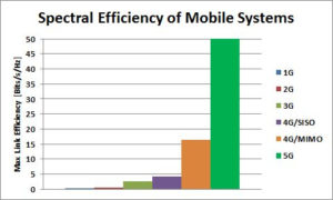
Spectrum Efficiency, this is the number of bits per bandwidth/Hz; 3x higher spectrum efficiencies are achievable.
Traffic Capacity, this is the number of users that can share the same network; 100x more traffics are achievable.
Network Efficiency, this is handling algorithms and time to make network connections between send and receive; 100x faster network response is achievable.
Energy Efficiency, this is the amount of energy needed to process data per bit; 100x lower energy is achievable.
5G Coding Options
There are 3 codes; LDPC, Polar, and Turbo, which are under investigations and considerations by 3GPP Standards working group for small block size of 5G Standard.
There are three considerations for choosing any coding for wireless communications; power [nJ/b], implementation [nm2/b], and latency [ns/b] efficiencies.
5G requires up to 1000 faster data rate than 4G, therefore the power efficiency has to be at least 1000 improved to even have the same battery life; otherwise it will be out in few seconds.
One way to mitigate the power and latency efficiencies; is to monitor every symbol SNR via CQI and only invoke full decoding at the receiver when SNR is near required threshold or high probability of error. The probability of bit error increases when the signal is close to noise level and vice versa. If the SNR is adequately high, say 6dB above threshold which means the desired signal voltage is twice as large of what is required; then decoding can be scaled down such that there is an additional gain on power and latency efficiencies.
Asymmetric Multilevel Outphasing (AMO) by Eta Devices
Envelop Tracking, aka ET, has been utilized to reduce the power consumption of Power Amplifiers, PA, near its maximum output power, by dynamically biasing the PA with absolute minimum voltage/current required, such that the PA efficiency increases to more than 50%. This technique relies on adjusting the bias voltage level of the PA for every symbol and can be applied for up to 20-40 MHz BW signal.
Patented by Eta Devices and acquired recently by Nokia, AMO is an enhanced ET technique which changes the PA bias level after few symbols, instead of every symbol. Therefore, AMO can be applied to signal up 160MHz BW, depending on the number of tracking symbols.
As a result of additional PA efficiency, simpler yet more efficient architectures and algorithms can be utilized for both BS and UE.
Analog vs. Digital Carrier Aggregation Architecture
LTE Carrier Aggregation, CA, is the latest advanced technique for achieving up to 600MBPS aka CAT12 throughputs. This is done by combining 3 down link, 3DL20MHz, bands data. Each channel can be either from the same or different bands, Intra or inter band, respectively.
From architecture stand point; there are 2 options to either aggregate the channels in Analog front end or digital base band. The natural question becomes which technique is more feasible.
Analog Carrier Aggregation Architecture
The channels have to be processed via single wide or broad band analog front end receiver, go through single wideband ADC and subsequent DSP.
Digital Carrier Aggregation Architecture
The channels have to be processed separately in 3 narrowband analog front end receiver, each goes through dedicated ADC, and then aggregation occurs in the base band via DSP.
It is not only the semiconductor real estate but also the power consumption and the flexibility/freedom of aggregating any channel is of a great concern, too.
Each technique above has its own challenges and benefits. The jury is out to decide which of these architectures is more feasible to handle CA efficiently.
5G Spectrum Allocations
On July 14th, FCC allocated 4 frequency bands above 24GHz to be used for 5G/next generation of wireless communication technology.
Here is snap shot of FCC ruling based on related documents.

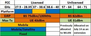
Qualcomm, Ericsson, Verizon, Nokia, Samsung, XO, Straight Path, CTIA, TIA, Fiber Tower, and Intel’s representatives requested greater than 62dBm/100MHz EIRP level which was apparently accepted by FCC.
Now that we have FCC ruling behind us, 5G technology design, development, and deployment would gear into higher speed by industry to meet at 2020 Tokyo Summer Olympic. This is generating larger momentum for new opportunities in high tech industry, especially in U.S.
3rd Industrial Revolution, aka 3rd Wave – 2020
Third wave will refer to advance of Mobile/Wireless Handheld Communications to its highest level and accessibility of massive amount of data/information instantly to mass populations. Just like 1st and 2nd industrial revolutions, many new jobs with more advanced skills will flourish while perhaps replacing some of the older jobs. Before 1990, we had to go to library to get access to books, journals, and scientific papers. With introduction of internet, we are now able to access all of the above from our convenient of office/home across the globe, so long as we are online.
5G will enable the same level of access from the mobile handset device that you carry as you roam across country. In addition, IoT will enable to control appliances and devices around your home and/or office from the very same mobile handset. New automobiles and Smart Cities will communicate with each other.
This level of connectivity and accessibility to information will be the 3rd Wave of industrial revolution.
With enablment of autonomous/self-deriving cars and its non-fault experience, automobile insurance policy may vanish. On the other hand, new opportunities for the cyber security will become top third of concern because of massive confidential data availability on the cloud.
Research and design can be decentralized to allow scientists to work from their own office where they choose.
Medical specialist such as radiologist will not necessarily have to go to hospital and/or clinic to work, as they can access patient data, evaluate, diagnose, and provide feedback from distance of their home office to staff and patients.
Real estate would change their business model to accommodate 5G and IoT technologies and change in demand for office buildings.
Online education will flourish and may replace traditional classroom for large scenarios.
Robot with analytic and learning skills will be introduced to consumer market.
Virtual reality will replace 2D video call for meeting family and friends. Soccer/football event in Germany could be seen in England in another stadium in 3D Video and Audio with Virtual Reality Network, VRN.
5G and IoT will touch every aspect of our lives; education, medical, transportation, communication, security, housing, entertainment, sports, and the way we conduct our job/work/business.
Looking Back/Rear View
In order to capture the trend of wireless communications technologies and industries, it is worthwhile to glance back at where we have traveled to get to this point in time. The following provides a brief history of Mobile Wireless Communication Systems and may lead us to envision some of the advances in technology that will come our way.
1G – 1980’s
The first wireless communication technology, 1G, relied on analog modulation which had been used over several decades prior to mobile communications for Radio and TV broadcasting applications. Like cars in early 1900, 1G was used by very limited population and perceived to be luxury for only voice communications. Front end architecture was super heterodyne. Today, 1G platform is no longer being used and obsoleted.
2G – 1990’s
The 2nd generation relied on digital wireless communication which enhanced spectrum efficiency, data security, and noise immunity over 1G. This was a huge leap over 1G and was more popular and available to larger populations. By this time, industries and investors had already realized the potential business and the expansions were happening at incredible speed. ZIF architecture became feasible and used for the 1st time in volume production of consumer electronics. AT&T has just announced that it will no longer support 2G platform. In spite of that, Middle East, China, India and perhaps African counties still rely on this technology for legacy and customer introductory services.
3G – 2000’s
Code Division Multiple Access, aka CDMA, was introduced and established by Qualcomm as the most efficient use of spectrum, hence more customers for service providers, and rapidly replaced 2G in North America and Europe, and is still creating new revenue/business in Asia and remaining countries. By now, wireless digital communication became the means of many new businesses around the globe. Telecommuting services starts being deployed. ZIF remained the architecture of choice for 3G front end.
4G – 2010’s
The need for higher data rate, bandwidth, and spectrum efficiency, brought Orthogonal Frequency Multiplexing Access, aka OFDM, for greater than 5MHz bandwidth requirements. This is the current technology of choice which has evolved into Carrier Aggregation, CA, over the past few years and will continue to do so, for next couple of years. The data rate and/or bandwidth are s
calable based on the user needs and service provider capacity. Envelope Tracking, ET algorithm is utilized for advanced Tx to enhance PA efficiency, i.e. battery recharge cycle. Multiple Inputs Multiple Outputs, aka MIMO is introduced in this technology.
5G – 2020 –Back to the Future…
Where would it take us?
5G relies on GaAs, GaN, SiGe, and CMOS
CMOS historically have been used for baseband signal processing in any radio technology and will continue at least be used due to it low cost and scalable geometry for the next 5 years.
Even though CMOS is trying to reach handset power amplification in 4G market, it is unlikely that it would succeed in mmW, due to limited breakdown voltage and power density.
On the other hand, GaAs has typically been used for handset market and will likely continued to be used for mmW.
GaN technology is being introduced to the market for that past decade and even though the cost per wafer is more expensive than alternatives, GaAs, CMOS, and SiGe, it will probably be the technology of choice for mmW Base Stations power amplifiers due to higher power density, 12W/mm, and breakdown voltage, 80V, in comparison to GaAs.
SiGe has been used on some mmW transceiver IC and probably will have some success capturing 5G market, as well. Also, wide bandwidth data converters may find their way through SiGe technology for 1Gbps sampling rate or higher.
Would 5G rely on DPA or DPD?
There are number of different linearization techniques which are used in Tx chain to increase the power efficiency of the transmitter, hence enhanced radio talk time. Recently, 4G and CA have utilized digital pre-distortion, aka DPD, technique to run handset PA along with ET at near compression point, such that optimum efficiency is achieved by corresponding PA. It is almost certain that DPD technique will be used for 5G technology as well.
On that other hand, Doherty Power Amplifiers, aka DPA, are gaining traction for CA and 5G base stations. Currently, they provide 60-65% efficiency utilizing legacy technique going back to 1936. However with some additional investment and work, there are potential opportunities to even further enhance that elegant design topology by William H. Doherty at Bell Lab.
Why 5G needs massive MIMO + BF at mmW Bands?
It is well known that MIMO increase the capacity/data rate by factor of M, i.e. the number of inputs/outputs antennas/sensors.
It is also well known that BF increase the directivity of desired signal, hence increased SNR, which also increases the capacity/data rate, albeit by log2 (SNR), i.e. slower rate increase relative to MIMO.
As frequency increases the wavelength decreases, therefore the antenna size and/or antenna array dimension decreases. As a result, at mmW band, it is possible to pack together a larger number of antennas to form the array for given area, which yields higher directivity, hence better SNR.
MIMO provides the same SINR for each UE, which is not typically an optimum and desired condition, as each user requires different data rate, hence difference SINR.
MIMO and BF simultaneously allows higher data rate as well as optimized SINR for each UE.
In light of the above, 5G mmW bands radio will utilize MIMO and BF, simultaneously. To support multiple UE, the number of antennas has to be much larger than the users, hence massive MIMO + BF.
MIMO and BF simultaneously allows higher data rate as well as optimized SINR for each UE.
In light of the above, 5G mmW bands radio will utilize MIMO and BF, simultaneously. To support multiple UE, the number of antennas has to be much larger than the users, hence massive MIMO + BF.
Analog vs. Digital Beamforming
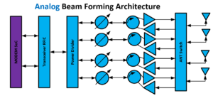
ABF
In Analog Beamforming, the amplitude and phase shifting occur in RF front end, hence in analog domain. Therefore, due to analog nature, in order to account for performance of amplitude and phase over frequency, temperature, voltage, and process (i.e. part to part), extensive characterization and meticulous calibration algorithms have to be done during the production phase, in addition to careful design topology.
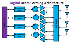
DBF
In Digital Beamforming, the amplitude and phase shifting occur in digital baseband. Therefore, there is no need for production calibration, due to maturity of digital process. This advantage does come at a price of additional DC power consumption for baseband IC.
HBF
In Hybrid Beamforming, the coarse amplitude and phase shifting occurs in analog domain, whereas the fine-tuning happens in digital domain. The HBF are feasible for very large antenna arrays, where ABF and DBF fail to scale due to complexity or power consumption, respectively.
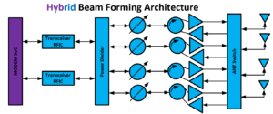
To select proper beamforming topology, careful analysis of use cases as well as complexity vs. power consumption trade-off analysis should be made to down select undesired customer limitations.
What is Radio Systems Engineering?
Radio systems engineer are responsible to review and capture overall radio requirements. The radio requirements could be divided into two major categories, Air and MODEM interfaces. Any radio design has at least two Systems Engineers, one for Air Interface, who is called Radio Frequency Systems Engineer, aka RF Systems Engineer, and second is Communication Systems Engineers, aka CommSys Engineer.
Air interface refers to the medium in which transmit and/or receive antennas of the radio operate in.
MODEM interface refers to baseband digital signal which has to be processed, via DSP, to decipher digital data after correcting errors incurred during the transmission and produces sent information for the radio user.
RF Systems and CommSys Engineers work together to decompose the Air and MODEM interfaces requirements.
In particular, RF Systems Engineer decomposes and defines every single block from Antenna down to A/D and D/A up to Antenna for Rx and Tx chains of the radio, respectively.
The CommSys Engineer decomposes and defines every single block inside the MODEM from synchronization, AGC algorithm, decryption/encryption, demodulation and modulation of Rx/Tx chains of the radio, respectively.
ORTENGA has seasoned systems engineering team who have previous industry design for supporting your radio project.
The following block diagram illustrates top level block diagram of any modern wireless digital communication systems.

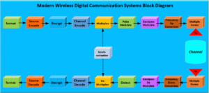
The Channel represents the Air Interface in the above block diagram.
Envelope Tracking Algorithm
Envelope Tracking, ET, Algorithm have mitigated Power Added Efficiency, PAE, of Power Amplifiers, PA, in UE as well as eNB infrastructure during that past decade.
It is well known that maximum PAE is reached when PA is near compression point. However, operating PA at or near compression point produces signal distortions due to non-linearity behavior of PA which effectively reduces EVM of transmitting signal, system KPI.
In order to mitigate the signal distortion, the PA nonlinearity can be simulated or characterized. Then the desired signal can be distorted intentionally prior feeding the PA in such a way that after the PA amplification, the desired signal becomes linear again. This algorithm is called Digital Pre Distortion, DPD, and widely used in UE, eNB, and gNB infrastructures.
Partner with ORTENGA to design and develop DPD and ET algorithms for your new product.
Radio Communications System and Radar Design Misconceptions
There are 4 major blocks in any Wireless Communication System or Radar applications which impact the key metric performances, namely; Antenna, Transceiver, Mixed Signal Converters, and MODEM.
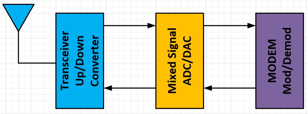
Antenna solely operates in radio frequencies. Transceiver operates in both radio and intermediate frequencies. Mixed Signal blocks either convert analog to digital or vice versa. MODEM solely operates in digital domain.
On the surface, it may appear that each major block is independent of other blocks or there is only dependency between adjacent blocks, e.g. Antenna and Transceiver. In a reality, all of these blocks are interdependent and designed precisely to interact with each other in tailored and optimized manner.
For instance, a MODEM can control and optimize antenna performances when the antenna switch from one frequency band to another or when Transceiver temperature changes over time.
An optimized radio or radar systems design take into account many interaction issues between each block and defines their performances that not only ensures their functionality but also operate with desired specifications as the environmental conditions around them changes. For instance, when you are using your mobile handset, depending how you hold the handset the antenna surrounding changes, therefore its input impedance changes, which in turn changes the efficiency of the antenna, if it is not properly retuned via MODEM.
It is also worth noting that there is no unique line up or unique requirements that works for 5G or IoT applications, each design would have its pros and cons, depending on which market and use cases are being targeted.
If you are designing any of the above blocks for 5G, IoT, or Radar markets, you should have radio systems engineers whom look into all of the interaction issues and validate any assumptions before requirements are locked in for designers.
In fact, SW and FW also have direct impact on HW and vice versa. Algorithms that control the radio front end and process the incoming and outgoing digital signals are implemented either in SW or FW within DSP core in the baseband unit or FPGA.
Consult with ORTENGA for your products’ requirements that may go into either Wireless Communication System or Radar system applications. ORTENGA provides you with analysis and computations to validate use cases target specifications and design goals.