- LEO SATCOM User Terminal (UT) Design Expertise
- What is LEO SATCOM?
- LEO SATCOM Opportunities and Challenges
- OneWeb LEO UT Prototype Architecture
- Why On-Board Processing Satellite Payload will be enabling LEO?
- Regenerative LEO Satellite Payload Architecture
- LEO SATCOM Beam Sequencing Requirements
- SATCOM Concatenated Coding
- What is the importance of G/T?
- LEO SATCOM Down-Link Throughput
- Impact of Antenna Efficiency on Antenna Temperature
- LEO UT SATCOM Architecture of Choice
- LEO UT SATCOM Business Opportunities
- OneWeb and SpaceX’s LEO UT SATCOM Limitations
- LEO UT SATCOM Pointing Angles Algorithm
- LEO vs. GEO UT SATCOM Requirements
- 5G, SATCOM, or Radar Filter Requirements
- Amazon Kuiper LEO UT SATCOM Flat Antenna Array
- Very Small Aperture Terminal, VSAT
- Signal Modulation
- Digital Signal Detection
- Digital Data Packet Quality of Service, QoS
- Amazon Kuiper LEO SATCOM Flat Antenna Array
- LEO vs. GEO UT Requirements
- LEO SATCOM Down-Link Throughput
- GEO and LEO SATCOM UT
- Enabler of AI into the Rural Areas
- Stationary LEO Is Mature. Mobile LEO Is the Multi-Billion-Dollar Frontier
LEO SATCOM User Terminal (UT) Design Expertise
LEO SATCOM User Terminal (UT) design and development expertise—from decomposing business requirements into technical specifications to delivering complete UT system analysis, architecture, and implementation.
ORTENGA provides seasoned engineering across Antenna, ASIC, or Algorithms domains, including their realization in hardware, firmware, and software.
We help businesses identify and define the technical features required to achieve their product and market objectives.
LEO SATCOM
LEO SATCOM stands for “Low Earth Orbit Satellite Communications”, see
below.

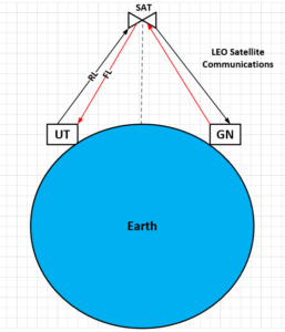
LEO satellites will be launching in 2019Q2 and will be operational in 2020Q2.
LEO is newer technology in comparison to GEO, Geostationary Earth Orbit, and requires less power, smaller size, while providing higher throughput/spectral efficiency.
To date, there are 26 companies making, User Terminals/UT, Satellite, Ground Network/GN products for LEO applications, excluding their vendors.
Significant venture capital is spent supporting many start-ups to capture this new SATCOM market.
LEO SATCOM UT Challenges and Opportunities
“LEO SATCOM Opportunities and Challenges” webinar sponsored by ORTENGA presented on June 18, 2020.
Encompassing LEO SATCOM attributes, describing various critical components, reviewing the market opportunities, and technical challenges is reviewed in the webinar.
OneWeb LEO UT Architecture
OneWeb has started validating the LEO UT Prototype based on Intellian MSA, SatixFy RFIC and SoC HW. The following diagram is simplified OneWeb LEO UT Prototype Architecture.
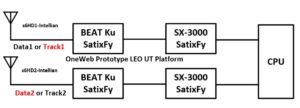
It is not clear whether these components reflect final design, yet are utilized to validate the Radio Link Budget as well as LEO DL Throughput.
Partner with ORTENGA to analyze LEO SATCOM Link Budget, identify Radio Front End, Transceiver, and MODEM chip sets/vendors, and design HW with down selected ASICs and appropriate algorithms to control beamforming architecture for your mobile product.
On-Board Processing Satellite Payload enabling LEO
Legacy GEO satellites non-regenerative, aka Bent Pipe Payload technology, were designed based on the constraints and requirements of 1960 – 2010 to save Size, Weight, and Power, SWaP, which ultimately impact cost.
Over the past two decades, the need for higher data capacity has grown significantly, from few hundreds Kbps to tens of Mbps, and continuing even steeper trends for the next decade.
Over the same period, the semiconductor geometry has decreased from 0.130um down to 7nm CMOS technology for digital signal processing at baseband. The electronics’ power consumption have also been reduced by implementing Sleep and Awake circuitry for the time of use, while reverse saturation current been directly proportional to the geometry.
Data capacity is dictated by Shannon Theory and is proportional to bandwidth and power, which are governed and restricted by FCC and ETSI.
In order to achieve higher throughput in the LEO SATCOM, architecture and system designers are taking a fresh look at new as well as legacy constraints and requirement to innovate alternative solution which addresses today’s consumer electronics product.
On Board Processing Payload allows the retrieve of data at satellite payload, which would remove/diminish satellites’ C/N and C/I dependency in the overall LEO Link Budget, consequently increasing the overall Eb/N0, hence better data throughput.
On Board Processing Payload not only has become possible, but also necessary to meet required data throughput for the next decade. LEO Payload satellites are being designed and developed with this new technology.
Partner with ORTENGA in designing the architecture and systems of LEO SATCOM products.
Regenerative LEO Satellite Payload Architecture
As LEO satellites designed and launched, some are based on legacy Bent Pipe Architecture and others are utilizing Regenerative, aka On Board Processing Payload Architecture. Regenerative LEO satellite architecture is more complex with the advantage of additional throughput relative to Bent Pipe system.
The following diagram illustrates top level Regenerative or On Board Processing LEO Payload.
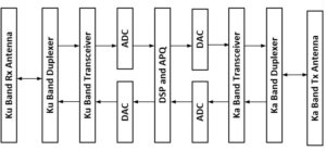
Design of the LEO payload requires analyzing and decomposing the system requirements to component level which will satisfy the overall expected throughput during the operation. It would, then, require down selecting appropriate vendors with specified semiconductor ASIC, designing HW with selected components, validating the design system level requirements via DOE before launching the payload.
Partner with ORTENGA in design and development of your LEO SAT Payload and/or LEO UT.
LEO UT SATCOM Beam Sequencing Requirements
In contrary to GEO satellites where they are in the orbit geostationary with respect to Earth, LEO satellites are passing by User Terminal, UT, every 10 – 20 seconds depending on the their altitude, the number of satellites in each orbital plane, and network coverage plan.
Therefore, LEO UT must be able to Beam Sequencing in very short period of time to track the moving LEO satellites while they keep connectivity with the satellites.
Consequently, the UT must either mechanically or electronically sequences its beam to keep the connectivity while it is tracking one satellite and hop to another moving satellite when the first satellite is out of sight.
This has implications on the how fast the beam has to form and on the technology of the beam steering mechanism.
Partner with ORTENGA to design and develop LEO Satellite or UT product.
SATCOM Concatenated Coding
The following diagram illustrates SATCOM concatenated coding architecture used between Satellite and UT.
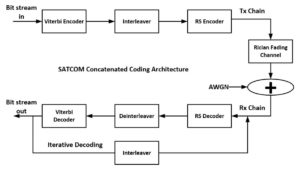
It is well known that Viterbi coding causes burst errors and RS coding is capable of removing several error simultaneously, therefore concatenated Viterbi and RS coding is a natural choice for SATCOM applications. Adding coding, error correction of digital signal enhances the radio communication performance by reducing the required transmit power for given BER, i.e. QoS, and/or increasing the range.
The tradeoff is in Latency as well as receiver decoder complexity and its implementation in the SoC.
SATCOM is utilizing concatenated coding architecture in which 2 layers of known coding are providing enhanced error corrections to reach QEF.
Let us know how ORTENGA can help in design and development of your radio communication systems.
What is the importance of G/T?
G/T stands for receiver Antenna Gain to Thermal Noise ratio. It turns out that C/N is directly proportional to G/T for any receiver. Therefore, the data rate or throughput is directly proportional to G/T.
For instance in SATCOM link, the receiver C/N reference to antenna terminal is directly proportional to G/T.
By carefully looking into the G/T metric, it becomes clear that just optimizing the antenna for its gain does not necessarily yields to a better C/N, as there is a trade-off between antenna gain and its thermal noise. Consequently, G/T is the metric to be optimized during antenna design.
Antenna temperature is function of its physical and brightness temperatures, as well as radiation efficiency.
Appropriate systems and architecture design takes into account the trade-offs and inherent relationships between these metrics to arrive at appropriate link budget and system behavioral model for computing C/N and throughput.
Partner ORTENGA for feasibility study, designing, and/or developing of your new radio communication systems architecture and definitions.
LEO SATCOM Down-Link Throughput
According to FCC regulations for Satellite EIRP, PFD on Earth, and analyzing, LEO Ku band User Terminal, UT, DL can have better than 10dB Eb/N0. By adding 8dB Turbo coding gain, that is ~18dB, conservatively. In other words, UT DL link can operate up to 256QAM Modulation and Coding Scheme, MCS, with existing MODEM SoC in the market.
The frequency reuse could be eight 250 MHz DL Channels for users in Ku Band, 10.7 – 12.7 GHz. Therefore the antenna requires 2 GHz bandwidth, albeit it could be dynamically tunable. Each of these 250 MHz channel is divided into multi access depending on the BW allocated by the network for each user. The user band selection occurs in the digital domain via MODEM SoC time slot partition. That is each UT process the 250 MHz band through RFFE and in the MODEM the data parsing and dedicated user data is selected.
Partner ORTENGA in designing and developing of your LEO SATCOM User Terminal.
ORTENGA will work with you to define Throughput/Availability of Network Resources, Assignment of Resources to each Customer, Coordination of Spectrum with regulatory organizations, FCC and ETSI, and other users of the spectrum, Optimization of Link budgets and System Trade-Offs.
ORTENGA will down select components such as SoC MODEM and Transceiver RFIC and required filtering which account for Thermal, Phase, I/Q imbalance, Nonlinearity, and Quantization noise, and Top Level Architectural documents for the Wireless System, AGC Algorithm and Gain Line up.
Impact of Antenna Efficiency on Antenna Temperature
Radio Communications Systems Engineers budget the noise impairments of each block in the system to limit it and design for adequate SINR. In spite of that, there is not much can be done to limit the noise contribution of the antenna itself, so it must be well understood before claiming design completion.
Antenna noise temperature is function of physical and brightness temperature. The physical temperature of the antenna is dictated by the antenna surrounding or ambient temperature.
Brightness temperature is the temperature that is seen by antenna based on its radiation pattern as well as environmental condition, profile or distribution of background temperature.
For instance, if the background temperature is constant, then the brightness temperature is background temperature. In SATCOM, the brightness temperature is not constant and depends on the pointing angle of the UT antenna.
As the antenna efficiency increase, the antenna temperature can converge to brightness temperature. In fact, if the radiation efficiency is 1, then antenna temperature is brightness temperature. On the other hand, when the radiation efficiency is zero, the other extreme, the antenna is a matched load and the antenna temperature is its physical temperature.
Partner ORTENGA in designing and developing of your Radio Communications System.
LEO UT SATCOM Architecture of Choice
Amazon, Facebook, Oneweb, and SpaceX all utilize Super Heterodyne LEO SATCOM radio architecture. The difference is that Amazon and SpaceX rely on legacy intermediate frequency, IF, while, Facebook and Oneweb are not. This implies difference frequency planning and capabilities of RF front ends, RFFE. Facebook and Oneweb architecture allow for higher datarate/throughput, ~7x. This is a significant advantage which could the data cost to the end user as well as bottom line difference, hence ROI.
AT&T seems to be relying on beamforming architecture for the electronically scanned antenna, ESA.
Almost all startups utilize Super Heterodyne radio architecture and legacy IF. This is due to the fact that they rely on COTS RFFE components.
Partner with ORTENGA to analyze LEO SATCOM Link Budget, identify Radio Front End, Transceiver, and MODEM chip sets/vendors, and design HW with down selected ASICs and appropriate algorithms to control beamforming architecture for your mobile product.
LEO UT SATCOM Business Opportunities
Low Earth Orbit Satellite Communication User Terminals, UT, are being designed and developed by many organizations as well as startup companies. In few short years, the demand for these LEO UTs will be significant. This is the growing sector of SATCOM markets for many years to come.
SpaceX and OneWeb have launched many LEO satellites already and plan to have and will continue to reach over 2000 satellites for phase 1. For every LEO satellites there would be between 100 – 1000 UTs. So taking a conservative estimate; there would 200000 UT at phase 1 of the LEO connectivity. Each UT could cost ~$2000 if it is stationary, FWA. That is $400M UT opportunity at phase 1.
Phase 2 of LEO UT would have mobile capabilities for Autonomous Automotive; namely ships, trains, cars, trucks, and plains. That is where the expected market opportunity would be at least 10 fold, $4B.
Augment ORTENGA in your design and development of LEO SATCOM product definitions to harvest this new market before it matures.
OneWeb and SpaceX’s LEO UT SATCOM Limitations
OneWeb and SpaceX have designed and are in the prototype phase of their LEO User Terminals.
While OneWeb relies on Mechanically Steered Antenna Array, SpaceX utilizes Phased Antenna Array technology.
In order to connect to first LEO satellite and handover to the second incoming LEO satellite, there is a tight time constraint, which Mechanically Steered Antenna Array solution requires two antennas. These antennas are typically dish antennas with high profile. This high profile limits these LEO UTs to Fixed Wireless Access, FWA, applications and market.
The Phased Array Antennas however are suitable for fast switching speed via single antenna array and can connect to LEO satellite 1 and handover to satellite 2, dynamically in order of ~100 us time, which are feasible for LEO requirements. However, Phased Array Antennas are expensive and typically used for military applications and cannot be streamed line for commercial applications.
There is a greater opportunity for Mobile LEO UT which neither of the above solutions address form technical and cost perspective. There is market for flat antenna array design in Ku and Ka bands. Flat Antenna Array is not only attractive for commercial applications but also addresses mobile LEO UT, such as Autonomous Automotive.
It is view of ORTENGA that cost effective Flat Antenna Array can be realized to address mobile market whether it is LEO or 3GPP Release 17 networks.
Augment ORTENGA with your design and development teams to address growing Autonomous Automotive markets.
LEO UT SATCOM Pointing Angles Algorithm
The following flow diagram illustrates LEO UT Pointing Angles Algorithm.
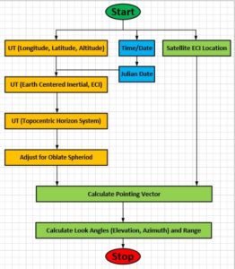
Obviously, additional Tracking Algorithm will be utilized due to LEO satellites’ handover.
Augment ORTENGA in your design and development of Antenna System Module, ASM, and algorithms development for LEO UT or gNB.
5G, SATCOM, or Radar Filter Requirements
Filters are widely used in radio communications and radar systems. In fact, multiple filters are used across any radio, namely; Preselector Filter, Image Rejection Filter, Channel Select Filter, Anti Aliasing Filter, Digital Filter in Decimation and Interpolation to cover some of them.
As the above filter names indicate, they impact anywhere from linearity, image rejection, resolution of ADC/DAC to DSP systems performances. There are tradeoffs where to put filter and set its requirements in such a way that optimizes the system performance over all operational conditions.
Filter requirements impact other blocks performance requirements, such as; PA, LNA, Mixer, ADC/DAC, PLL, and Antenna. There are multiple Filter Topologies in Analog or Digital domains, such as; Butterworth, Tchebyshev, Elliptical, Bartlett, Hanning, Hamming, Blackman/Harris, or Kaiser filter. Analog filters are implemented in the frequency domain, while digital filters are in time domain.
It is challenging task to relate each filter requirements to actual system metrics at radio level. It requires both understanding of systems as well as impairments caused by lack of adequate filtering to draw and analyze appropriate filtering and implement them at the proper stage in the radio.
These filters are used in UE Mobile Wireless, UT SATCOM, SATCOM HUB, Mobile Infrastructures, and Radar Systems. If your system has Rx Sensitivity, interference, blocker, simultaneous listens and talks, ADC/DAC clipping issues, then it may need additional filtering or filtering at proper stage to mitigate the issues.
Partner with ORTENGA to analyze, drive appropriate Filter requirements, and/or implement the desired filter in Analog or Digital domain for your new product and market.
Amazon Kuiper LEO UT SATCOM Flat Antenna Array
Recently, Amazon published some information about innovative LEO SATCOM Flat Antenna Array.
Forensic engineering of this information and combining with LEO SATCOM link budget, one can come to the following conclusions.
These conclusions have to be verified via appropriate experiments; however they reveal how close Amazon is in achieving their desired goal, i.e. realization of LEO SATCOM flat antenna and appropriate global LEO UT.
Based on Amazon publication, the target throughput is 400 Mbps, i.e. maximum. Then, it is safe to assume that Amazon customers could expect nominal target throughput of up to 200 Mbps.
Downlink Ku band is 17.7 – 19.3 GHz, BW = 1.6 GHz or FBW = 8.7%. That implies Q = 11.55 = ~12 for antenna array, feed, and impedance matching networks, which is technically feasible.
The DL antenna apparently is comprised of roughly 400 elements, i.e. maximum AF = 26dBi.
On the other hand, given diameter is 12” or 30 cm, a maximum/theoretical directivity of 35dBi, therefore element factor of ~9 dBi. That implies the antenna elements are not omnidirectional, e.g. dipole or monopole.
Although, the antenna may be tunable/configurable via FPGA firmware/software to accommodate the DL band, the instantaneous fractional bandwidth for optimum performance could be between 100 – 200 MHz. Thus in the downlink mode, there are 8 to 16 sub-bands that to support 1.6 GHz.
Each frame is comprised of Preamble for which Security/Authenticity, Synchronizations, and Tx to Rx handshake, Inner and Outer Coding implemented before Data transfer. Therefore, spectral efficiency can be in order of ~2/3 of each frame.
Typical SATCOM active antenna noise temperatures are between; 100 – 200 K. Therefore, expected G/T for this antenna could be ~10 dB/K.
In order to achieve 100 Mbps or faster throughput, 64QAM or higher has to be achieved, respectively. Although the above antenna can deliver Eb/N0 = 8dB, the required MODEM has to lock at Eb/N0 <=-10dB via FEC.
There are only handfuls of companies which have MODEM IP technology and engineering knowhow that can deliver Eb/N0 <= -10dB.
Some of the MODEMs have diversity capabilities which make it convenient for satellite handover or beam handover, required features and prime value proposition of LEO SATCOM UT. These MODEMs also save the cost for secondary MODEM, PCB real estates, and BOM.
Later, perhaps end of this or early next year, when the flat antenna array, front end module, and MODEM are integrated as a part of User Terminal, the MODEM capability can be verified.
ORTENGA is a consulting firm which provides product engineering capability evaluations by reviewing published data and analyzing its technical implications and researching competitive product landscape.
Very Small Aperture Terminal
VSAT are ground SATCOM User Terminals, UT, which have 75 cm to 1.2 m antenna aperture.
Although VSAT are typically utilized for GEO SATCOM Networks market, the growth is in LEO market for the next several years.
LEO networks will provide higher datarate and lower latency relative to legacy GEO networks, comparable to 4G 3GPP.
Many companies are designing and developing LEO Hub, UT, and/or Satellites, which will be online as early as 2021.
Partner with ORTENGA for Market analysis and/or Competitor landscape for your new product.
Signal Modulation
In radio communication, the signal of interest is typically not at the radio frequencies.
In general radio frequencies, RF refers to frequencies at which a realizable size antenna can be utilized to covert electrons to photons, hence radio wave propagations. Therefore, there are at least two frequencies, one of the signals the other of the carrier, RF. The carrier is meant as the means to propagates between transmit to receive antennas. The method in which the signals of interest alter the carrier frequency, RF, is called modulation.
Here are some legacy modulation techniques which everyone uses in their daily life.
Amplitude Modulation, aka AM used in your car AM radio. The signals of interest alter the carrier amplitude, i.e. the amplitude of the carrier is the information which is meant for the receiver. This legacy modulation technique is susceptible to multipath fading. As you drive under a highway bridge, you notice that the AM radio audio signal is momentarily lost and comes back. This phenomenon is caused by multiple bounces of radio signal waves against the bridge and reaching your car radio. These radio waves sometime cancel each other and other time add constructively. The radio wave cancellation is fading of the signals of interest.
Frequency Modulation, aka FM used in your car FM radio to address multipath fading. While you are listening to FM radio under the highway bridge, you would not experience any loss of signal.
The above modulations are analog method of modulation. Nowadays, there more advance digital modulations. Digital modulations have three advantages over analog modulation.
- Spectrally more efficient over analog counter part
- More immune to noise, i.e. requires lower SNR for signal detections and discern
- More secure, as digital code changed between the transmitter and receiver
For the above reasons, digital modulations are ubiquitous.
Binary Phase Shift Keying, aka BPSK is the most basic digital modulation. The signals of interest are binary and embedded in the phase, 0 vs. 180 degrees of the carrier.
Quadrature Phase Shift Keying, aka QPSK is another digital modulation. The signals of interest are 2 bits and embedded as 45, 135, 225, 315 degrees phase of the carrier.
The binary codes are digital alphabet of modulation language.
It turns out the as the number of alphabets, bits increased, the more information can be encoded in the carrier, i.e. more spectrally efficient, bps/Hz.
On the other hand, as the number of alphabets, bits increased, additional signal to noise, SNR is required. In other words, the signals of interest are less immune to noise, consequently, additional power is required.
This is a challenge that communication engineering needs to balance, the trade off between spectral vs. power efficiency, hence digital modulation scheme design.
Partner with ORTENGA to design your product.
Digital Signal Detection
Analog signal and digital signal have different signal detection threshold.
Digital signal detection threshold is lower than analog signal detection.
While analog signal detection has a gray performance, digital signal detection is binary.
Technically, regardless of analog or digital a signal is detected when the signal is above the detection amplitude threshold.
Anything below the detection threshold amplitude is considered noise and ignored, while anything above the detection threshold amplitude is considered the signal of interest.
Therefore, the detection threshold differentiates signal from noise.
The detection threshold could be absolute in amplitude or relative to noise floor of the receiver via SINR or SNR.
The SINR or SNR is predetermined and programmed into the receiver FW.
Unlike communication signals where the receivers have error corrections capabilities due to redundancy, in radar applications there is no error correction, therefore there is a small chance of false alarm, i.e., appearance of target detection due to noise yet there is no actual target.
Consequently, signal detection threshold applies to radar signal for given false alarm rate.
ORTENGA helps businesses to identify required technical features to realize their business goals.
Partner ORTENGA in your next product concept, design, and development to realize that business goal.
ORTENGA has seasoned engineering from Autonomous Automotive, SATCOM, radar, Smart City, WiFi, and Mobile Terrestrial Radio Communications industries in Antenna, ASIC, HW, FW, and SW engineering disciplines.
Digital Data Packet Quality of Service, QoS
Digital Data Packet Quality of Service, QoS should be application dependent.
For audio signal, e.g., phone call, human ears cannot distinguish better than 1 bit error in 1000 bits, i.e., BER = 1e-3.
Therefore, the QoS for audio call is BER ≤ 1e-3.
For visual signal, e.g., TV movie or picture human eyes have much higher resolution, 1 bit error in 1000,000,000, i.e., BER = 1e-9.
Therefore, the QoS for TV picture is BER ≤ 1e-9.
Combining these observations with Water Fall Curves, they reveal that as the BER decreases required Eb/N0 increases.
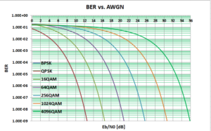
The Water Fall Curves reveal that as the spectral efficiency increase the required Eb/N0 is also increases, for given QoS which depends on the application.
ORTENGA has seasoned engineering from Autonomous Automotive, SATCOM, radar, Smart City, WiFi, and Mobile Terrestrial Radio Communications System industries in Antenna, ASIC, Algorithm, HW, FW, and SW engineering disciplines.
Partner with ORTENGA to define and develop your new product.
Amazon Kuiper LEO SATCOM Flat Antenna Array
Recently, Amazon published some information about innovative LEO SATCOM Flat Antenna Array.
Forensic engineering of this information and combining with LEO SATCOM link budget, one can come to the following conclusions.
These conclusions have to be verified via appropriate experiments; however they reveal how close Amazon is in achieving their desired goal, i.e. realization of LEO SATCOM flat antenna and appropriate global LEO UT.
Based on Amazon publication, the target throughput is 400 Mbps, i.e. maximum. Then, it is safe to assume that Amazon customers could expect nominal target throughput of up to 200 Mbps.
Downlink Ku band is 17.7 – 19.3 GHz, BW = 1.6 GHz or FBW = 8.7%. That implies Q = 11.55 = ~12 for antenna array, feed, and impedance matching networks, which is technically feasible.
The DL antenna apparently is comprised of roughly 400 elements, i.e. maximum AF = 26dBi.
On the other hand, given diameter is 12” or 30 cm, a maximum/theoretical directivity of 35dBi, therefore element factor of ~9 dBi. That implies the antenna elements are not omnidirectional, e.g. dipole or monopole.
Although, the antenna may be tunable/configurable via FPGA firmware/software to accommodate the DL band, the instantaneous fractional bandwidth for optimum performance could be between 100 – 200 MHz. Thus in the downlink mode, there are 8 to 16 sub-bands that to support 1.6 GHz.
Each frame is comprised of Preamble for which Security/Authenticity, Synchronizations, and Tx to Rx handshake, Inner and Outer Coding implemented before Data transfer. Therefore, spectral efficiency can be in order of ~2/3 of each frame.
Typical SATCOM active antenna noise temperatures are between; 100 – 200 K. Therefore, expected G/T for this antenna could be ~10 dB/K.
In order to achieve 100 Mbps or faster throughput, 64QAM or higher has to be achieved, respectively. Although the above antenna can deliver Eb/N0 = 8dB, the required MODEM has to lock at Eb/N0 <=-10dB via FEC.
There are only handfuls of companies which have MODEM IP technology and engineering knowhow that can deliver Eb/N0 <= -10dB.
Some of the MODEMs have diversity capabilities which make it convenient for satellite handover or beam handover, required features and prime value proposition of LEO SATCOM UT. These MODEMs also save the cost for secondary MODEM, PCB real estates, and BOM.
Later, perhaps end of this or early next year, when the flat antenna array, front end module, and MODEM are integrated as a part of User Terminal, the MODEM capability can be verified.
ORTENGA is a consulting firm which provides product engineering capability evaluations by reviewing published data and analyzing its technical implications and researching competitive product landscape.
ORTENGA helps businesses to identify required technical features to realize their business goals.
Partner ORTENGA in your next product concept, design, and development to realize that business goal.
ORTENGA has seasoned engineering from Autonomous Automotive, SATCOM, radar, Smart City, WiFi, and Mobile Terrestrial Radio Communications industries in Antenna, ASIC, HW, FW, and SW engineering disciplines.
LEO vs. GEO UT Requirements
Low Earth Orbit, LEO UT has distinct differences which can make or break Geostationary Earth Orbit, GEO UT.
- LEO satellites are mobile relative to UT on Earth therefore, UT has to not only point to the satellites but also track the satellite and then switch to another mobile satellite coming into range.
- LEO UT have only point +/- 45 from broadside, therefore there is better link connectivity no matter where the UT is on earth.
- LEO satellites are at fraction of distance relative to GEO satellites form earth, therefore the latency is fraction of GEO link, ~60ms, as well as fraction of EIRP, therefore less transmit power is required, for uplink or Reverse Link, RL.
Items 2 and 3 above appear less stringent requirements for LEO relative to GEO.
However, regarding item 3, G/T requirement is similar to GEO UT given required throughput, which is the most challenging implications of UT requirements. Regarding item 1, it has some subtle yet challenging implications which become new requirements.
This one requirement can make or break legacy design, if LEO UT is not designed properly. The UT must find the LEO satellites in blink of an eye and track it for ~10 seconds before switching to another LEO satellite.
This occurs over and over to keep the radio link without interruption. In addition, if UT is itself mobile, then the challenge of finding LEO satellite and switching to another every ~10 seconds becomes exponentially more difficult.
That is where LEO UT needs robust beamforming, beam tracking, and SLL management algorithms that work dynamically on the fly. These algorithms work hand in hand with Antenna Module.
There is additional requirement for Bandwidth. LEO radio links are supposed to provide a better throughput.
This additional throughput requirement is achieved by two system metrics. First a better C/N or Eb/N0 which yield better spectral efficiency is required. Second a wider operation bandwidth is required of the Antenna, Transceiver, and MODEM.
The above requirements are challenging and many engineering teams across the globe are trying to innovate commercial grade solutions.
It is worth to mention that LEO UT can significantly cost less than GEO counterpart for two reasons.
The MODEM and FEM ASIC can be leveraged from cellular market, if properly architected, defined, and selected. GEO UT operates at order of magnitude higher transmit power and costs between 20 – 30 % overall UT, whereas LEO UT requires much lower power and smaller factor of FEM.
Augment ORTENGA into your design and development of LEO UT team for successful applications of requirements and their implementations.
LEO SATCOM Down-Link Throughput
According to FCC regulations for Satellite EIRP, PFD on Earth, and analyzing, LEO Ku band User Terminal, UT, DL can have better than 10dB Eb/N0. By adding 8dB Turbo coding gain, that is ~18dB, conservatively. In other words, UT DL link can operate up to 256QAM Modulation and Coding Scheme, MCS, with existing MODEM SoC in the market.
The frequency reuse could be eight 250 MHz DL Channels for users in Ku Band, 10.7 – 12.7 GHz. Therefore the antenna requires 2 GHz bandwidth, albeit it could be dynamically tunable. Each of these 250 MHz channel is divided into multi access depending on the BW allocated by the network for each user. The user band selection occurs in the digital domain via MODEM SoC time slot partition. That is each UT process the 250 MHz band through RFFE and in the MODEM the data parsing and dedicated user data is selected.
Partner ORTENGA in designing and developing of your LEO SATCOM User Terminal.
ORTENGA will work with you to define Throughput/Availability of Network Resources, Assignment of Resources to each Customer, Coordination of Spectrum with regulatory organizations, FCC and ETSI, and other users of the spectrum, Optimization of Link budgets and System Trade-Offs.
ORTENGA will down select components such as SoC MODEM and Transceiver RFIC and required filtering which account for Thermal, Phase, I/Q imbalance, Nonlinearity, and Quantization noise, and Top Level Architectural documents for the Wireless System, AGC Algorithm and Gain Line up.
GEO and LEO SATCOM UT
GEO SATCOM connectivity is a legacy technology and is comparable to 3G Terrestrial connectivity.
New SATCOM technology which is under development and taking shape for global connectivity coverage utilizes LEO satellite constellations.
LEO satellites are much closer to Earth compare to GEO satellites, therefore there is significant power saving for radio transmission.
Consequently, the LEO UT radio front end does not require bulky Block Up Converter, BUC.
For instance, GEO and LEO BUCs are in order of 20 W and 2 W, respectively, an order of magnitude different.
In addition, the waveform generation and signal detection algorithms as well as frequency selective filters are distinctly different, therefore HW/FW/SW would be different.
Multiband Antenna can support both GEO and LEO, once designed properly.
Partner with ORTENGA to design and develop LEO UT.
Enabler of AI into the Rural Areas
It is well known that rural areas do not experience the same wireless connectivity coverage in comparison to the urban areas.
The prime factor has been due to the lack of adequate wireless connectivity coverage via Terrestrial technology, eNB or gNB for examples.
Artificial Intelligence, AI is based on connectivity to world wide web or internet.
With advancement of LEO SATCOM and its penetration into commercial market, the wireless connectivity imbalance between rural and urban areas would diminish.
This is due to the LEO SATCOM global reach.
As the internet availability becomes less expensive and readily more available to every corner of the Earth, the AI would consequently penetrate into the rural areas.
ORTENGA helps businesses to identify required technical features to realize their business goals.
Stationary LEO Is Mature. Mobile LEO Is the Multi-Billion-Dollar Frontier
Why User Terminal Architecture Must Evolve for High-Speed Platforms
Low Earth Orbit SATCOM has crossed its first milestone.
Flat electronically steered antennas are deployed.
Constellations are operational.
Fixed wireless access works.
Stationary LEO user terminals are no longer experimental.
Mobility, however, is not an incremental extension of stationary design.
It is a fundamentally different architectural regime.
From Stability to Dynamics
In stationary LEO:
- The satellite moves.
- The terminal does not.
In mobile LEO:
- The satellite moves.
- The terminal moves.
The antenna beam must continuously resolve a dual-motion geometry problem.
Tracking becomes a closed-loop dynamic control system integrating:
- Satellite ephemeris
- Terminal position and velocity
- Vehicle orientation (roll, pitch, yaw)
- Continuous Doppler compensation
- Real-time coordinate transformation
This is not simply antenna steering.
It is predictive system orchestration under motion.

Minutes of Visibility, Seconds of Decision
A LEO satellite remains visible for only a few minutes.
Continuity is not achieved by one satellite.
It is achieved by seamless handoff.
To preserve uninterrupted service, the terminal must:
- Predict the next satellite
- Acquire it before the current link degrades
- Lock timing and frequency in advance
- Transfer traffic before link margin collapses
Mobility compresses the timing window because:
- Elevation angle changes more rapidly
- Doppler shifts continuously
- Vehicle motion adds angular rate and blockage risk
Handoff must be predictive — not reactive.
Beam Splitting vs Beam Sequencing
To achieve make-before-break continuity, a mobile terminal must either:
Split the beam
or
Sequence the beam at ultra-high speed
Beam Splitting
Two beams are formed simultaneously:
- One toward the current satellite
- One toward the incoming satellite
But splitting reduces effective aperture gain per beam.
Both radio links must remain above decoding threshold during overlap.
If link margin is insufficient, continuity fails.
Beam Sequencing
The full aperture alternates rapidly between satellites.
This preserves instantaneous gain but demands:
- Microsecond-scale switching
- Deterministic latency
- Stable phase and frequency tracking
Either approach requires disciplined link margin management.
Mobility makes that management more complex.
The 9 Engineering Challenges of Mobile LEO
Mobile LEO user terminals must solve nine tightly coupled constraints:
- Dual-motion tracking — Satellite and terminal move simultaneously.
- Seamless make-before-break handoff — No session interruption.
- Link margin preservation during overlap — SNR must remain above threshold.
- Ultra-fast beam control — Deterministic steering and switching.
- Doppler on Doppler — Satellite and vehicle velocity compensation.
- Vibration and orientation stability — Maintain phase coherence under motion.
- Thermal constraints — Roof-mounted, sealed, high-temperature environments.
- Vehicle electrical envelope constraints — Limited continuous current allocation and system-level integration.
- Fleet-scale cost optimization — Architecture must scale economically across large deployments.
These variables are interdependent.
Higher gain narrows beamwidth.
Narrower beamwidth increases pointing precision requirements.
Faster control increases processing load.
Processing load increases electrical and thermal stress.
Mobility compresses the entire system envelope.

Link Margin Is the Silent Constraint
At Ku and Ka band:
- Beamwidth is narrow.
- Elevation angle loss is real.
- Atmospheric attenuation is significant.
During handoff:
- Slant range increases.
- Geometry degrades.
If beam splitting reduces gain while elevation drops, SNR may fall below decoding threshold.
The transition must begin while margin is still healthy.
This is not merely a steering problem.
It is a link budget orchestration problem.
Thermal and Electrical Integration
Mobile platforms operate within:
- Sealed enclosures
- Elevated roof temperatures
- Constrained vehicle electrical allocations
- Automotive qualification requirements
Electrical integration is not about nominal voltage.
It is about allowable continuous current, transient behavior, EMC compliance, and system-level load coordination.
Thermal and electrical constraints must be architected early — not adjusted later.
ORTENGA Framework: Audit → Design → Validate
Mobility requires disciplined progression from concept to verified performance.
Phase 1 — Audit
Define What the Product Must Do
Audit is product concept definition.
This phase establishes:
- Target mobility scenarios (passenger vehicle, fleet, maritime, defense)
- Operational speed and motion profiles
- Required continuity level (consumer-grade vs mission-critical)
- Mechanical and aerodynamic integration constraints
- Environmental and qualification targets
- Vehicle electrical integration boundaries
- Market positioning and cost tier
This is where features are defined:
- Continuous mobility support
- Seamless make-before-break handoff
- Dual-motion tracking capability
- NTN interoperability
- Automotive-grade robustness
No architecture decisions are finalized here.
The outcome is a clearly defined capability envelope.
Phase 2 — Design
Engineer How the Product Will Achieve It
With use cases defined, architecture begins.
This phase determines:
- Aperture size vs beamwidth trade-offs
- Beam splitting or sequencing strategy
- RF chain topology
- Sensor fusion integration
- Predictive handoff control logic
- Thermal architecture
- Electrical system integration
Modeling includes:
- Link margin analysis
- Motion simulation
- Doppler compensation evaluation
- Control loop stability verification
The outcome is a system architecture aligned to the Audit-defined intent.
Phase 3 — Validate
Implement and Verify Against Audit Use Cases
Validation includes both implementation and confirmation.
It requires:
- Building the hardware and software architecture
- Testing under defined mobility scenarios
- Verifying seamless handoff under motion
- Confirming thermal and electrical compliance
- Measuring performance against defined continuity targets
- Ensuring the product fulfills the original Phase 1 use cases
Validation closes the loop between concept and real-world performance.
The Multi-Billion-Dollar Frontier
Industry projections for non-terrestrial networks indicate substantial growth over the next decade.
Fixed broadband proved feasibility.
Mobility defines scalability:
- Autonomous automotive
- Commercial fleets
- Maritime mobility
- Aviation connectivity
The next competitive advantage will not come from larger arrays alone.
It will come from disciplined system architecture.
How ORTENGA Supports Mobile LEO Programs
Mobile LEO user terminals demand architecture discipline before capital is committed.
ORTENGA supports engineering and executive teams through:
- Audit — Defining product use cases and mobility feature envelopes
- Design — Architecting aperture, RF, beam management, and system integration
- Validate — Implementing and verifying performance against real-world motion scenarios
Early architectural decisions determine cost, electrical viability, thermal stability, and scalability.
If your organization is evaluating or developing a mobile LEO user terminal platform, defining the right product concept before hardware commitment is the most critical step.
Mobility is not an incremental antenna upgrade.
It is a system architecture challenge.
And disciplined progression from concept to validated performance defines who leads the next phase of LEO deployment.