Algorithm Engineering Realizations — From Mathematical Models to System Reality
ORTENGA supports algorithm engineering programs across wireless,
SATCOM, radar, sensing, beamforming, embedded intelligence,
and next-generation silicon-to-system platforms.
We help organizations translate deployment realities,
hardware constraints,
subsystem interaction,
latency requirements,
and operational objectives
into executable algorithm architectures and validated system outcomes.
System Before Algorithm.
Architecture Before Optimization.
Validation Before Scale.
Why Algorithm Programs Underperform
Algorithm correctness does not guarantee system success.
Many algorithm programs underperform not because the algorithm fails mathematically,
but because system constraints,
interfaces,
and cross-domain interdependencies
were poorly defined and only exposed during validation.
Advanced algorithms cannot compensate for flawed system assumptions.
Algorithm Realization Across System Architecture
Every radio and radar system fundamentally contains four major functional domains:
- Antenna System Module (ASM)
- Front-End Module (FEM)
- Transceiver Module (TRM)
- Baseband Module (BBM)
Algorithms primarily execute within the BBM,
but their performance depends on RF interaction,
subsystem interfaces,
ASIC architecture,
latency constraints,
memory bandwidth,
and deployment realities across the complete system.
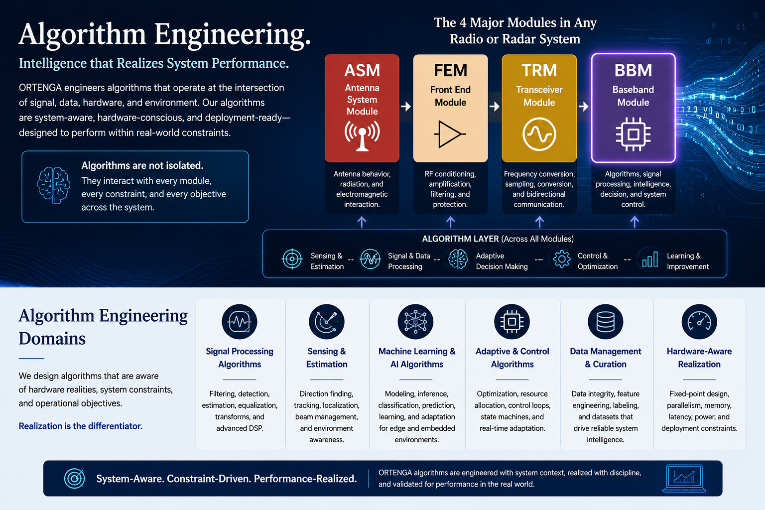
Algorithms do not operate in isolation.
Successful algorithm realization depends on alignment between mathematical intent,
hardware realities,
subsystem interfaces,
deployment environments,
and operational objectives.
Algorithm Engineering Domains
Structured realization environments spanning wireless,
sensing,
adaptive systems,
embedded DSP,
and edge intelligence.
Wireless & SATCOM Algorithms
Wireless synchronization,
modem processing,
adaptive communications,
and deployment-aware signal processing.
Radar & Sensing Algorithms
Detection,
tracking,
waveform processing,
adaptive sensing,
and real-time system integration.
Beamforming & Adaptive Systems
Adaptive arrays,
calibration,
MIMO processing,
spatial filtering,
and antenna-to-baseband coordination.
Embedded DSP & Hardware-Constrained
Fixed-point DSP,
FPGA and ARM realization,
ADC calibration,
and hardware-aware embedded processing.
AI, Edge Intelligence & System Realization
Machine learning,
edge intelligence,
AI-assisted RF processing,
data curation,
and deployment-aware validation.
Assess Algorithm Realization Risk Before Deployment Lock-In
Product success depends on whether algorithms remain aligned with
system architecture,
hardware realities,
subsystem interaction,
deployment environments,
validation objectives,
and operational outcomes.
Successful algorithm realization depends on alignment between mathematical intent,
hardware realities,
deployment constraints,
validation behavior,
and business objectives.