- Antenna Array Pattern Including Mutual Coupling
- Radar Ghost Target
- Antenna Array Far Field Radiation Pattern
- Radar Pulse Compression
- 5G Coding Options
- Radar Market Opportunities
- Pulsed Radar Architecture
- Radar equations, how many are there?
- Sivers IMA’s view on mmW fronthaul for 5G C-RAN
- What is Clutter?
- Asymmetric Multilevel Outphasing (AMO)by Eta Devices
- Interference Cancellation
- X50 Qualcomm MODEM
- 3D mmW Radar for Automotive
- High Definition Sub Channels AM/FM Radio Market
- Analog vs. Digital Carrier Aggregation Architecture
- iPhone7 Tear Down Results
- How to avoid Robocalls?
- MIMO vs. Beamforming
- Quantum Computing, QC
- Apple RFIC Market Entry
- Similarities of Filter vs. Antenna
- 5G Smart Phone Functional Block Diagram vs. Process Technologies
- 5G MODEM/SoC design and development race is underway
- 5G Spectrum Allocations
- Google Mobile Device/Phone
- Qualcomm 5G New Radio
- The Next Generation of Wearable is Here
- Third Wave
- 5G and IoT Technologies Wave
- Looking Back/Rear View
- 5G – 2020 –Back to the Future…
- 5G Outlook
Antenna Array Pattern Including Mutual Coupling
When calculating antenna array pattern for complete accuracy, the pattern of an array antenna must include the variations in the excitation currents as well as the pattern of each element acting under the influence of all coupling effects. This is a difficult task if not impossible; however there are 2 techniques for addressing this problem, namely; isolated element and active element pattern approach. In the isolated element pattern approach, the coupling effect is accounted for in the current excitation and is appropriate for very large arrays. In the active element pattern approach, all coupling effects are accounted for through the active element.
Inquiry send to: info@ortenga.net
Posted on December 28, 2016
Radar Ghost Target
In radar processing, ghost target appears when there is a multipath of echo signal reaching receiver. This causes the receiver having difficulty in differentiating, identifying, and tracking the actual target.
Automotive radar experiences moving target as well as the radar equipment, which further exacerbates this ghost target vision situation and requires appropriate radar signal and data processing, in addition to front end HW.
The echo signal typically could have either Rician or Rayleigh profile for small scale fading.
In order to mitigate ghost target vision, there are 2 parameters that have to be carefully analyzed and designed, namely; signal BW and symbol rate. These parameters are the knobs to avoid signal dispersion and time variant channel, respectively. Obviously, understanding the multipath fading manifestation is fundamental in solving problems at hand.
Inquiry send to: info@ortenga.net
Posted on December 27, 2016
Antenna Array Far Field Radiation Pattern
Antenna arrays are used to achieve higher directivity relative to the array element.
The radiation pattern of an array can be computed as
Far Field Radiation Pattern = |EF*PF*AF|2
where, EF, PF, and AF are Element Factor, Pattern Factor, and Array Factor.
Element Factor is infinitesimal factor of single element antenna
Pattern Factor is radiation pattern of single antenna due to its current distribution over the antenna
Array Factor is radiation pattern of array due to isotropic element
Each of the above factors can be computed standalone and their products is Far Field Radiation Pattern of the array.
For instance, Marconi-Franklin Linear array antennas are stacked 3 dipole antenna. The element factor is Hertzian dipole pattern. The Pattern factor is the radiation pattern of single dipole due to sinusoidal current excitation or distribution. And the Array factor is the pattern due to isotropic elements array.
Inquiry send to: info@ortenga.net
Posted on December 23, 2016
Radar Pulse Compression
As Radar technology becomes part of automotive and commercial drones, new requirements are developed to provide for this new market appropriately. Some of the technical challenges to be addressed are stringent range and radial velocity resolution for moving target as well as radar itself. It is well known that range resolution requires lower PRF, while radial velocity resolution requires higher PRF. Obviously both requirements cannot be met, simultaneously. Pulse compression technique is used to mitigate this issue. PN pulses can be used in a way that can produce optimum resolution for both range and radial velocity. Barker code of various lengths provides an example of PN pulses.
Inquiry send to: info@ortenga.net
Posted on December 8, 2016
5G Coding Options
There are 3 codes; LDPC, Polar, and Turbo, which are under investigations and considerations by 3GPP Standards working group for small block size of 5G Standard.
There are three considerations for choosing any coding for wireless communications; power [nJ/b], implementation [nm2/b], and latency [ns/b] efficiencies.
5G requires up to 1000 faster data rate than 4G, therefore the power efficiency has to be at least 1000 improved to even have the same battery life; otherwise it will be out in few seconds.
One way to mitigate the power and latency efficiencies; is to monitor every symbol SNR via CQI and only invoke full decoding at the receiver when SNR is near required threshold or high probability of error. The probability of bit error increases when the signal is close to noise level and vice versa. If the SNR is adequately high, say 6dB above threshold which means the desired signal voltage is twice as large of what is required; then decoding can be scaled down such that there is an additional gain on power and latency efficiencies.
Inquiry send to: info@ortenga.net
Posted on November 23, 2016
Radar Market Opportunities
Radar market for automotive is growing at rapid pace and will have annual growth rate for the next decade. Currently radars are used as advanced feature for some high end automobiles. As radar and its added safety features are becoming norm in automobiles and even trucks, the market grows significantly. It is expected that future cars will have multiple radars for various direction and range. In fact radars will be utilized in consumer electronics drone in cities. The following chart shows radar market opportunities outlook for the next decade. Semiconductor industry is investing in design and development of mmW IC and BBU of radar system electronics.
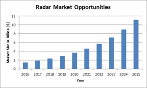
New antenna structures such metamaterials are used to eliminate phase shifters and potentially reduce cost for phased array technology in some of the advanced radars.
Inquiry send to: info@ortenga.net
Posted on November 20, 2016
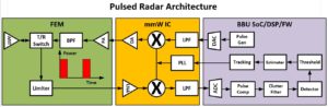
Pulsed Radar Architecture
Pulsed radars are becoming more popular due to digital capability of pulse generation and detection, hence integrated circuits smaller geometry/die size, as well as enhanced range and radial velocity resolutions by appropriating designing pulse waveforms and repetitions. The following is a typical pulse radar functional block diagram. It should be mentioned that the electronic circuits for basic mmW radar could be as small as a smart phone. And, for more stringent radar requirements, the overall physical size can grow to accommodate several antennas and the corresponding front ends’ HW. Nowadays, radars are becoming part of automotive features and in few short years every autonomous car will be equipped with multiple radars. Any advanced radar can have the capabilities to calibrate for environment in which it operates at, to reduce clutter and enhances SNR to improve radar performances.
Inquiry send to: info@ortenga.net
Posted on November 15, 2016
Radar equations, how many are there?
Radar equation relates transmit and received antenna gain, power, radar cross section, operating wavelength/frequency, range, and noise. Consequently, radar signal to noise ratio can be computed. There are 3 classes of radar; Search, Track, and Weather, each with its own radar equation which are used to relate physical design parameters to performance metric of a given radar.
Radar engineers use appropriate equation for designing and modeling given radar. Search radar is utilized to scan given sky volume to find target, an obvious example is airport radar. Tracking radar is utilized to lock onto a target and track its movement. Whereas, Weather radar is utilized to analyze precipitations and movement of rain, snow, and/or storm.
Some important observations regarding radar equations are that Track and Weather radar equations have squared wavelength dependency, whereas Search radar does not, directly. On the other hand, Track and Search radar equations have inverse quartic range dependency, whereas Weather radar has only inverse squared range dependency.
It should be noted that there other differences between each radar equation. Interested readers can contact ORTENGA for additional information.
Inquiry send to: info@ortenga.net
Posted on November 9, 2016
Sivers IMA’s view on mmW fronthaul for 5G C-RAN
There is a race to release 5G solutions before the World Radio Communication Conference 2019 (WRC-19). Some of the main drivers are operators in the US, Japan and South Korea.
At WRC-19 there will be a final decision on the frequencies that will be used. However, FCC has already shared some of the new bands that will be available in the US:
- 28GHz (27.5-28.35GHz)
- 37GHz (37-38.6GHz)
- 39GHz (38.6-40GHz)
- 60 GHz (57-71GHz)
30 GHz-300 GHz has been defined as millimeter wave bands (mm-wave), hence all the new 5G frequency bands allocated by FCC can out of simplicity be defined as mm-wave. The first mm-wave frequencies that will be used for the cellular access scenario, seems to be 28 GHz which was recently confirmed by Qualcomm releasing information about their new Snapdragon X50 5G modem. Samples of the X50 modem will be available in the second half of 2017, with production in the first half of 2018, which means that the first mm-wave solution in handsets will be available in 2018. The Qualcomm X50 modem is promising speeds of up to 5 Gbps. IEEE have released 802.11ad for operation in the 60 GHz band, which support data speeds of up to 7 Gbps. In 2019, IEEE will also release the 802.11ay standard, which is an add-on to the 802.11ad standard, supporting data speeds of up to 20–40 Gbps. One of the most important 5G access performance requirements is latency, with latency requirements below 1 ms (sometimes <5 ms), to be compared with a latency in the range of 70-90ms as is the case in today´s LTE networks.
One proposed architecture for 5G base stations is Cloud-RAN (C-RAN), where the RF Transceiver is separated from the baseband unit (BBU) in a so called remote radio head (RRH). The digital baseband signals are carried to the RRH via either mm-wave or optical fiber, which is referred to as fronthaul. Fronthaul for C-RAN is often using the Open Base Station Architecture Initiative (OBSAI) and the Common Public Radio Interface (CPRI). The communication between the RRH module and the BBU requires very high bit rates and low latency (<100 µs). Today CPRI fronthaul may vary from approximately 0.6 Gbps up to approximately 9 Gbps depending on the type of LTE configuration that is supported. Conventionally, the CPRI specifications are designed for communication over fiber optic cables. However, CPRI based communication can also be used in wireless mm-wave fronthaul. For locations without fiber access, mm-wave is a very cost effective solution. However, CPRI has been shown to suffer from low transmission efficiency, poor scalability and limited flexibility, making it unsuitable for many of the future 5G fronthaul use cases. The latest CPRI Specification V7.0, defines line bit rates of up to 24 Gbps. With such data speeds already used for 4G+, even higher data speeds would be required for 5G. Therefore, many players within the eco-system are working on alternative interfaces, e.g. the IEEE working group is working on the Next Generation Fronthaul Interface [1] as an alternative to CPRI. The EU project 5G -Crosshaul [2] is focusing on integrated front and backhaul and proposes a unified multilayer data plane encompassing innovative high-capacity transmission technologies and novel deterministic latency switch architectures with the 5G -Crosshaul Packet Forwarding Element (XFE) and the unified 5G -Crosshaul Common Frame (XCF) format. The 5G-Crosshaul EU-project has shown that a packet based fronthaul interface is having less-stringent requirements compared to CPRI, where the packet based XCF will also support IEEE 802.11ad links (and eventually also 802.11ay is our guess). Another group within the CPRI Industry Initiative is working a new Specification called eCPRI, with 5G Front-haul support, this is expected to be released in August 2017. One of their focuses is to enable a ten-fold reduction of the required bandwidth
In June 2016 [3], the average CPRI connection speed is between 5-6 Gbps and as operators deploy LTE-Advanced features, the requirements on the CPRI links will keep on increasing. There are currently wireless mm-wave technologies that can support a data speed of up to 10 Gbps with low latency, which support CPRI V6.0 line data rates. These kinds of solutions will also support some of the LTE-Advanced uses cases and some of the initial 5G fronthaul line rates. For example, the Maxlinear (former Broadcom) BCM85100 Frequency Division Duplex (FDD) mm-wave modem uses two separate communications channels for simultaneous send and receive operation in the 60 GHz band, resulting in 10 Gbps data speed and latency below 100 µs (one way). As Broadcom share in [4], the BCM85100 PHY layer Maximum latency is less than 40 µs (one way, with a mm-wave link distance at 2.5Km with 99,999% up time). This modem meet both the speed and latency requirement for wireless fronthaul. Using the Broadcom BCM85100 with the new Sivers IMA mm-wave transceiver [5], which supports 64QAM modulation with its built in VCO will be sufficient for the average CPRI connection speed of today. Using a 2 GHz bandwidth and 128 QAM, the full 10 Gbps speed is achieved. One weakness with the traditional point to point mm-wave solution is that beam steering and beam forming functionality is lacking, which is a quite important to have, for easy installation of the RRH with little time wasted on link alignment.
Which technology could support 5G fronthaul and still be cost effective? Let us list the main requirements:
- Link speeds of 20-40 Gbps
- <100 µs latency
- Easy installation
- Fronthaul Interface that does not require +100 Gbps
I believe by using the 60 GHz mm-wave band and 802.11ad/ay technology with some small modification as well as a smart packet based fronthaul Interface will be a very good solution for 5G fronthaul.
This then provides the following parts to offer cost effect fronthaul using mm-wave:
- Speed >20 Gbps
- Low latency, can be reach via using FDD “operation” (<100 µs) with 802.11ad/ay technology, with 14 GHz of available bandwidth in US.
- 11ad/ay has support for beam steering and beam forming, making installations quick and easy.
- Using the 5G-Crosshaul Packet Forwarding Element (XFE) and Common Frame (XCF) format with 11ad/ay, or possibly using the Next Generation Fronthaul Interface will solve the low transmission efficiency, poor scalability and limited flexibility which we today see for 5G CPRI.
Sivers IMA will be presenting at the IWPC conference 16-18 November “What Role Will mmWave Technologies Play in 5G?” in San Jose, CA USA.
Anders Stormis the CEO of Sivers IMA. Sivers IMA is the technology leader within millimeter wave solutions.
Sivers IMA is working in the forefront of new technology within micro- and millimeter wave with a
focus on RFICs, transceivers, converters, WiGig (802.11ad/ay) for data and telecom infrastructure,
backhaul, RAN network evolution, VCOs, beam steering, phased arrays, FMCW radars and more.
Anders has over 20 years of experience from data and telecommunication.
Sivers IMA is a leading manufacturer of micro- and millimeter wave products for connecting and quantifying a networked world. Sivers IMA has a long history and is internationally renowned as a reliable supplier of high quality components used in telecommunications links, RADAR sensors and test & measurement equipment. Headquarters is located north of Stockholm in Kista, Sweden.
Ref [1] IEEE, Next Generation Fronthaul Interface (NGFI) Working Group
Ref [5] http://www.google.com/patents/EP2582108A2?cl=en
Ref [6] http://siversima.com/wp-content/uploads/PB_TRX-1608-LT6275.pdf
Any input, feedback, and/or inquire should be sent to: info@ortenga.net
Posted on November 1, 2016
What is Clutter?
Clutter is legacy radar terminology for background noise of target under surveillance, TUS. Radar engineers make clear distinction between noises vs. clutter. Noise is an unwanted signal that typically generated inherently by electronic systems, such as receiver. Typical radio impairments are due thermal, phase error/time jitter, and quantization which are associated with noise.
Clutter on the other hand is the unwanted signal picked up by the antenna or antenna array in the radar system. Typically, radiation pattern of antenna consists of main lobe, side lobes, and back lobe. The main lobe is wanted whereas side lobes and back lobe are unwanted radiations. During signal reception, the side lobes and back lobe are also picking up signal, which is not from the target under surveillance. Since the side lobes and back lobe are much lower level below the main lobe, the unwanted signal contributions due by them are also weaker within the receiver, nevertheless the clutter exist and needs to be quantified. Therefore, radar systems engineers include clutter in the link budget of radar receiver.
Inquire at info@ortenga.net.
Posted on October 27, 2016
Asymmetric Multilevel Outphasing (AMO)by Eta Devices
Envelop Tracking, aka ET, has been utilized to reduce the power consumption of Power Amplifiers, PA, near its maximum output power, by dynamically biasing the PA with absolute minimum voltage/current required, such that the PA efficiency increases to more than 50%. This technique relies on adjusting the bias voltage level of the PA for every symbol and can be applied for up to 20-40 MHz BW signal.
Patented by Eta Devices and acquired recently by Nokia, AMO is an enhanced ET technique which changes the PA bias level after few symbols, instead of every symbol. Therefore, AMO can be applied to signal up 160MHz BW, depending on the number of tracking symbols.
As a result of additional PA efficiency, simpler yet more efficient architectures and algorithms can be utilized for both BS and UE.
Inquire at info@ortenga.net.
Posted on October 26, 2016
Interference Cancellation
Radio interference cancellation is a technique in which the interfering radio signal is suppressed by placing a null in radiation pattern of antenna or antenna array systems. Far Field or Fraunhofer radiation pattern of an antenna is function of current or field distribution over the antenna aperture.
Antenna proximity can be divided to 3 regions; Reactive near field, Radiating /Fresnel near field, and Far Field/Fraunhofer. Radio communication energy is targeted for Far Field of an Antenna.
The idea of radio interference cancellation via radiation pattern is similar to suppressing an unwanted signal via filter. In fact, antenna is a “spatial filter”, see Similarities of Filter vs. Antenna, posted on August 5th. This technique assumes that the direction of interfering signal is prior knowledge or dynamically can be detected. By forming antenna arrays, the radiation pattern of over antenna array can be adjusted dynamically via phase relationship between each antenna feeding. Alternatively, if the radio interfering signal is placed at side lobe of the radiation pattern, the unwanted signal strength can be adjusted via current or field distribution of antenna array.
5G technology will be utilizing interference cancellation technique to overcome unwanted signals.
Inquire at info@ortenga.net.
Posted on October 24, 2016
X50 Qualcomm MODEM
Recently, Qualcomm made a press release regarding 5G MODEM 10nm SoC, aka X50, and its capabilities. The 5G NR has 3 radios, first one at 28GHz range with 5Gbps data rate and less than 100m range, 2nd radio is using bands between 1 – 6 GHz, aka mid band, and carrier aggregation technology, and 3rd radio is below 1GHz with available BW.
28GHz mmW band provide the maximum data rate with minimum range via beamforming technology, and when the radio signal is getting weak below certain threshold, there is a handoff to the strongest signal available in mid or low band. The Mid and low bands are using MIMO, 802.11 and/or 4G Technologies. Mid band provides data rate of 1Gbps for the same range. The low band provides the longest range with the lowest data rate, depending on the available BW. The handoff algorithm appears to be working from any bands to another, depending on the RSSI level for the radio with higher data rate.
X50 is the first MODEM with multi platforms handoff capabilities to converge 4G, 802.11, into 5G technology and expected to sample and production launch in 2017 and 2018, respectively.
Inquire at info@ortenga.net.
Posted on October 19, 2016
3D mmW Radar for Automotive
Radio Detection and Ranging, aka radar, has been used since WWII in military applications, then in Avionic, and recently entered into Automobile applications. Automotive radar equipment are typically used for Collision Avoidance, however as Autonomous Car is becoming reality within few short years via advancement of wireless mobile communications, 5G, and connected cities, IoT, 3D mmW Radar will find its way into next generations of cars.
Originally, radar was meant to detect and provide the distance/range to the target. Then, it evolved to provide the speed of the target using Doppler frequency shift of the Electromagnetic, EM, echo signal. It further enhanced to estimate Time of Arrival, ToA, then Direction of Arrival, DoA, using pulsed waveform and measuring the round trip time of the echo signal. The EM echo is created by reflection from the target. Target effective area seen by radar is called, Radar Cross Section, RCS. Each target has its own radar signature/RCS and can be cataloged and used for identification with advance digital signal processing of the EM echo signal, aka radar signature. Radars are characterized either by CW or Pulsed modulation. CW radar is better for frequency resolution of the echo, which translate to speed of the target, whereas Pulsed radar is better suited for time resolution of the echo, which translate to ToA. 3D mmW radar will provide 3 dimensional field of view of the car.
There have been handfuls of companies that make radar units for car manufacturers. Now that the market is growing exponentially and the car radar is more than feature on high end cars, automobile manufacturers have started investing internally on radar technology design and development.
To learn more about the automotive radar technology and its market, inquire at info@ortenga.net.
Posted on September 30, 2016
High Definition Sub Channels AM/FM Radio Market
Although, FCC and ETSI have long licensed digital broadcasting AM and FM radio stations, the High Definition, aka HD, radio broadcasting is taking shape nowadays. Many radio stations have started implementing HD radio channels along with legacy analog for the very same station/channel. That has created a new trend of HW and equipment demands for HD broadcast, car and handheld receivers in consumer market industry. For instance some FM radio stations are introducing up to 3 HD channels for the same band. Each HD channel is broadcasting different program, independently.
With the advancement of smart phone and radio stream capabilities, radio receiver has lost some ground during the past several years. However, HD radio is gaining some momentum by being used as emergency means of communications. It is safe to predict that HD radio will still be used in Africa, Middle East, Central Asia, and South America for communications and in Northern America and Europe for emergency responders.
Any input, feedback, and/or inquire should be sent to: info@ortenga.net
Posted on September 25, 2016
Analog vs. Digital Carrier Aggregation Architecture
LTE Carrier Aggregation, CA, is the latest advanced technique for achieving up to 600MBPS aka CAT12 throughputs. This is done by combining 3 down link, 3DL20MHz, bands data. Each channel can be either from the same or different bands, Intra or inter band, respectively.
From architecture stand point; there are 2 options to either aggregate the channels in Analog front end or digital base band. The natural question becomes which technique is more feasible.
Analog Carrier Aggregation Architecture
The channels have to be processed via single wide or broad band analog front end receiver, go through single wideband ADC and subsequent DSP.
Digital Carrier Aggregation Architecture
The channels have to be processed separately in 3 narrowband analog front end receiver, each goes through dedicated ADC, and then aggregation occurs in the base band via DSP.
It is not only the semiconductor real estate but also the power consumption and the flexibility/freedom of aggregating any channel is of a great concern, too.
Each technique above has its own challenges and benefits. The jury is out to decide which of these architectures is more feasible to handle CA efficiently.
Any input, feedback, and/or inquire should be sent to: info@ortenga.net
Posted on September 23, 2016
iPhone7 Tear Down Results
There are significant changes between iPhone7 relative to 6, starting with, 2 MODEM, Intel and Qualcomm.
Intel and Qualcomm MODEM are supporting ATT/T-Mobile and Verizon/Sprint carriers, respectively.
The RF front ends are also significantly different between Intel and Qualcomm baseband SoC.
There are over 30 various passive filters in each iPhone.
The followings are snap shots of both flavor of iPhone7 and respective silicon real estates for benefited companies.

Total Bill of Material cost is less than $300.00, while Retail price is at $749.00
Any input, feedback, and/or inquire should be sent to: info@ortenga.net
Posted on September 19, 2016
The Lumigon T3 Smart Phone Launches with MediaTek AP/MODEM
Lumigon is the new Danish Smart Phone manufacture and launching T3 model.
The Lumigon T3 Smart Phone model is using MediaTek X10 Helio 2.2GHz 64Bit Application Processor and 4 FDD and TDD LTE MODEM 28nm SoC. This HD 4.8” touch screen display has 802.11ac dual band, BT, BLE, NFC connectivity, and infrared transceiver. T3 model is equipped with GSM Quad, UMTS Quad, LTE Penta, and GPS GLONASS/BEIDOU radio bands.
T3 is based on Android 6.0 with 4MP night vision camera, first smart phone, 3GB RAM, 128GB memory and water resistance chassis.
Posted on September 16, 2016
Send your input and/or feedback via email to info@ortenga.net
How to avoid Robocalls?
I get several Robot Calls, aka Robocall, every day. It varies from IRS impersonator with thick foreign accent, Windows Tech Support who pretends to be in Atlanta, GA but does not know the local time there, research firm with long list of questioner, cold sales call from home/office improvement vendors or service contractors, local politician who runs for an office with political speech, and the list goes on.
Even though, it is entertaining in some aspect, since I have a brand new story to tell my family at the dinner table every night, but it becomes time consuming and distracting when you are in middle of an important business.
Wouldn’t’ be nice at this day and age, have an automated answer machine which is smart enough to pick up every call at the first ring, ask some typical questions that we can program into, and only notify us when the caller meets our criteria for legitimate call to respond to?
If this project interest you and willing to work on it, let’s start the conversation.
Contact me: info@ortenga.net
Posted on September 15, 2016
MIMO vs. Beamforming
MIMO is based on multiple antennas similar to antenna array however each antenna is working independently of other antennas. The overall data is decomposed to lower data rate and each antenna is transmitting portion of that data, independently. In essence MIMO is using spatial diversity and multiplexing for very high data rate transmission. The spacing between each antenna is a wavelength to create adequate isolation while uncorrelated signals are picked up by each antenna.
Beamforming is achieved via Phased Array Antennas. The Phased Array Antennas are based on array technologies which have been used extensively in military applications in the past 4 decades. The antenna arrays electronically steers the beam to illuminate the intended target. The beam steering occurs via changing the relative phase of each antenna element, such that the overall beam is formed of construction of Electromagnetic Waves at desired direction in the far field and produce higher SNR compare to single antenna at the receiver end. The Phased Array Antennas are working together to achieve high gain/directional antenna, hence higher SNR at the receiver. The spacing between each antenna element is typically half wavelength to avoid grating lobe.
5G Technology will be utilizing massive MIMO as well as Beamforming, BF. Massive MIMO is intended for below 6GHz, whereas BF will be used for mmW bands (i.e. where wavelength is in order of mm, e.g. 30GHz).
Posted on September 4, 2016
Send your input and/or feedback via email to info@ortenga.net
Quantum Computing, QC
By 2017, CMOS semiconductor technology is reaching to 7nm gate-length. That means in just a few short years, the CMOS technology could reach to less than nm or atom level gate-length. Once that occurs, the classical deterministic mechanic theory and circuit logic model break down and will not hold anymore. As a result, Quantum Mechanics phenomena, such as; Superposition and Entanglement theory will need to be used. In 1952, Schrodinger formulated an equation which describes how the quantum state changes with time. Post 2020 computers technology will be based on Quantum Computing, QC, techniques with capabilities to handle more sophisticated calculations and optimizations which are not feasible today and could drive future generation of application processors.
Several companies are investing on QC, such as; Google, Intel, IBM, Microsoft, D-Wave, and Rigetti QC.
Posted on August 27, 2016
Send your input and/or feedback via email to info@ortenga.net
Apple RFIC Market Entry
Apple is preparing the launch of its own RFIC for some of its product lines.
RFIC production ramp is expected to be in 3Q2017 and potential product could be Ipad and/or Macbook’s Wireless Connectivity, WLAN.
It appears that Apple is still facing some issues with mastering iPhone front end RFIC architecture and design, as it is much more challenging requirements. The target iPhone RFIC launch roadmap is 4Q2019.
Posted on August 9, 2016
Send your input and/or feedback via email to info@ortenga.net
Similarities of Filter vs. Antenna
From the electrical engineering perspective, a filter is a device that passes signals of interest in the desired frequency band while discriminating other/undesired frequencies.
An antenna is typically considered a transducer device, which converts guided electromagnetic waves to spherical waves.
Both filters and antennas are typically passive devices and reciprocal (i.e. input and output can be swapped). What is less known about antenna, yet can be mathematically shown is that it behaves as a “spatial filter”.
From the Fourier Transform theory, we know that a narrow pulse, in time domain, has a wide frequency/spectral content (i.e. time and frequency are reciprocal to each other). To pass such a narrow pulse signal, a wide band filter is required. Similarly, a narrow far-field antenna radiation pattern requires to pass wide “spatial frequencies”. In other words, the antenna has to be electrically large (i.e. relative to wavelength). That is why, in the radio astronomy community, an antenna is viewed as “spatial filter”.
Posted on August 5, 2016
Send your input and/or feedback via email to info@ortenga.net
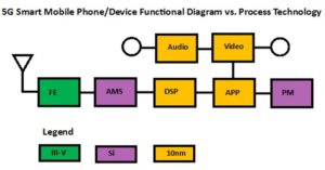
5G Smart Phone Functional Block Diagram vs. Process Technologies
5G air interface will be in mmW bands and require additional capabilities from semiconductor in addition to Silicon. It is widely believed that III-V compound semiconductor will have a place in the front end, FE, at least for PA. Depending on the 5G architecture chosen and implemented, there could be other devices that would also rely on III-V compound.
Analog Mixed Signal, AMS, blocks will still be on Silicon.
Digital base band blocks will all be in Silicon with 10nm FinFET CMOS geometry or less. Intel and TSMC are developing 7nm process technology for 2017 launch, which would be the state of art at the time. Mask Layers tapeout will cost more than 10M$, originally. Therefore, it is a significant cost for startups and costly to tolerate design issues and/or library models inaccuracies.
Appropriate architecture, topology, and design of SoC MODEM will be the key for the winner of 5G market SoC/MODEM.
Posted on August 1, 2016
Send your input and/or feedback via email to info@ortenga.net
5G MODEM/SoC design and development race is underway
Now that FCC allocated 5G spectrum and standardization is on fast track and perhaps expediting. The race for 5G MODEM design and development is underway. There are several known players, such as; Qualcomm, Samsung, MediaTek, Apple, Avago, Ericsson, and Intel. There are also some lesser known startups which their focus is solely on this next generation of wireless communication systems.
2017 will be marked as the first 5G MODEM/SoC test chip by handful semiconductor companies which would be verifying their new architecture, topology, design, and sub 10nm geometry process.
Send your input and/or feedback via email to info@ortenga.net
Posted on July 29, 2016
5G Spectrum Allocations
On July 14th, FCC allocated 4 frequency bands above 24GHz to be used for 5G/next generation of wireless communication technology.
Here is snap shot of FCC ruling based on related documents.

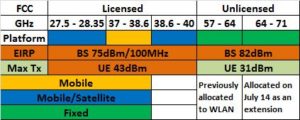
Qualcomm, Ericsson, Verizon, Nokia, Samsung, XO, Straight Path, CTIA, TIA, Fiber Tower, and Intel’s representatives requested greater than 62dBm/100MHz EIRP level which was apparently accepted by FCC.
Now that we have FCC ruling behind us, 5G technology design, development, and deployment would gear into higher speed by industry to meet at 2020 Tokyo Summer Olympic. This is generating larger momentum for new opportunities in high tech industry, especially in U.S.
Posted on July 15, 2016
Send your input and/or feedback via email to info@ortenga.net
Google Mobile Device/Phone
Google has been working on Mobile HW for the past few years and is expected to release its Mobile Device/Phone in the last quarter of 2016. Google has already established relationship with Infineon and using their RFIC transceiver for front end. The MODEM to be used, however, is not revealed. There are 4 choices in front of Google for MODEM silicon; Qualcomm, Intel, MediaTek, and Samsung. In few short months, we will know who is chosen by Google.
Posted on July 3, 2016
Send your input and/or feedback via email to info@ortenga.net
Qualcomm 5G New Radio
On June 27, Qualcomm announced a sub 6GHz 5G prototype new radio, NR, that is tailored version of its existing 802.11ac product line with albeit different modem, which “also supports a new integrated subframe design for significantly lower over-the-air latency than what is possible in today’s 4G LTE network. The new prototype adds to Qualcomm Technologies’ existing 5G mmWave prototype system, operating at 28 GHz and capable of robust mobile broadband communications in non-line-of-sight environment, utilizing advanced beamforming and beam-steering techniques.” Qualcomm is planning to showcase this NR at Mobile World Congress Shanghai held from June 29 to July 1, Qualcomm booth in Hall N2 booth C38. The estimated range appears to be less than 100m for full 6.93Gbps throughput and meant for indoor non-line of sight, NLOS, environment.
Posted on June 27, 2016
Send your input and/or feedback via email to info@ortenga.net
The Next Generation of Wearable is Here
Cicret is about to release the next generation of wearable technology, Bracelet, which is waterproof and provides bigger and more accessible interface, while it is small and light enough to be carried with you anywhere.
Take a look …https://cicret.com/wordpress/?p=32830
Posted on June 11, 2016
Send your input and/or feedback via email to info@ortenga.net
Soli (Gesture Controlled Wearable)
On May 29th Google released video of Soli project. Soli consists of 60GHz Infineon transceiver radar (radio detection and ranging) 28nm CMOS IC based on 802.11ad Standard. Radar works based on electromagnetic waves echo from objects within its view. Soli also uses phase array antenna technology. According to Google, “Soli has no moving parts and fits onto a chip and consumes little energy”. This is a game changer for new gadget in consumer electronics and will find many applications. If you are interested, read more at the link below;https://atap.google.com/soli/
Posted on June 6, 2016
Inquire via email to info@ortenga.net
Third Wave
Technology advancement is continuous throughout the time.
It is widely believed that there has been couple of significant changes/revolution within the industry already.
1st Industrial Revolution – ~1800
The 1st revolution occurred when power steam engines consequently locomotive were invented.
That changed the productivity level to higher volume and differentiated advanced technological from traditional communities.
2nd Industrial Revolution – ~1900
The 2nd revolution occurred when electricity and automobile were invented.
Electricity created many new jobs/opportunities such as electrician and electrical engineers in electrical appliance manufacturing/industry.
Travelling became more common and personalized as a result of automobile. Roads constructions, automotive parts manufacturing, auto mechanics were new jobs to name some examples.
3rd Industrial Revolution, aka 3rd Wave – 2020
Third wave will refer to advance of Mobile/Wireless Handheld Communications to its highest level and accessibility of massive amount of data/information instantly to mass populations. Just like 1st and 2nd industrial revolutions, many new jobs with more advanced skills will flourish while perhaps replacing some of the older jobs. Before 1990, we had to go to library to get access to books, journals, and scientific papers. With introduction of internet, we are now able to access all of the above from our convenient of office/home across the globe, so long as we are online.
5G will enable the same level of access from the mobile handset device that you carry as you roam across country. In addition, IoT will enable to control appliances and devices around your home and/or office from the very same mobile handset. New automobiles and Smart Cities will communicate with each other.
This level of connectivity and accessibility to information will be the 3rd Wave of industrial revolution.
With enablement of autonomous/self-deriving cars and its non-fault experience, automobile insurance policy may vanish. On the other hand, new opportunities for the cyber security will become top third of concern because of massive confidential data availability on the cloud.
Research and design can be decentralized to allow scientists to work from their own office where they choose.
Medical specialist such as radiologist will not necessarily have to go to hospital and/or clinic to work, as they can access patient data, evaluate, diagnose, and provide feedback from distance of their home office to staff and patients.
Real estate would change their business model to accommodate 5G and IoT technologies and change in demand for office buildings.
Online education will flourish and may replace traditional classroom for large scenarios.
Robot with analytic and learning skills will be introduced to consumer market.
Virtual reality will replace 2D video call for meeting family and friends. Soccer/football event in Germany could be seen in England in another stadium in 3D Video and Audio with Virtual Reality Network, VRN.
5G and IoT will touch every aspect of our lives; education, medical, transportation, communication, security, housing, entertainment, sports, and the way we conduct our job/work/business.

Posted on April 10, 2016
Send your input and/or feedback via email to info@ortenga.net
5G and IoT Technologies Wave
2016
FCC and ITU will allocate 5G spectrum, after which, IEEE and 5GPPP are expected to release 5G Mobile Standards. This will enable the industry to effectively put together resources to work on 5G product roadmap. There are some obvious companies that we know of, and some others who are not on radar but will be involved, such as; Insurance and Cyber Security firms.
2017
Carriers
Carriers will begin their base station design and development. Some already have head start with R&D expenditure in previous years and some level of infrastructure designed, yet still have to finalize their product definitions, design, and launch development process into full gear.
Semiconductor
Semiconductor companies will finalize their product definitions, such as; MODEM architecture, coding techniques, data converters and RF/Microwave front end requirements. It is worth mentioning that larger companies already have test chip for 5G architectures, by then, they will organically assign/new hire for design and development teams. PA, ADC/DAC, and MODEM requirements will be completely revolutionary in design goals, not only support over 1GHz bandwidth also with power consumption of at least one order of magnitude less. Antenna and PA designers will have plenty of new opportunities. While III-V semiconductor materials will become reality in consumer electronics for mass production.
New Servers architectures with tremendous work load capacity will be designed.
Automotive
This will be the next big wave of significant changes to automotive industry. Autonomous/self-driving vehicles will be the target. This would trigger a complete vertical change of ecosystem which supports that industry including insurance company’s business model or lack thereof for insuring non-fault vehicles.
Insurance
Insurance companies will change their business model from ground up in order to take into account 5G and IoT technologies wave.
Cyber Security
With capabilities of 5G and IoT, Cyber Security will be on the top 3 list of importance and this industry will begin to exponentially grow to address various new businesses related to 5G and IoT technologies wave.
2018
The first 5G MODEM Silicon and mmW Front End III-V will be available for design verification. Trial Servers and Base Stations will be deployed across various Northern America, Europe, and Asia.
Field and Network verification will be conducted in metropolitan.
2019
The first wave of handheld mobile 5G devices will be available in Asia. By now, many cities have already implemented thousands of wireless sensors to acquire and report data, while, the network is still being developed. Issues reported in field will be addressed by appropriate SW download.
2020
Consumer interests and engagements will be valued by carriers with special early deals for conversion to 5G. Metropolitan 5G networks and services will be installed and verified across multiple cities around globe.
5G and IoT technologies wave arrives at Northern America, Europe, and Asia.
Internet of Things, IoT, will be new reality.
The first 5G ecosystems will be available just in time for Tokyo Olympic via 1st Tier manufacturers.
Posted on April 1, 2016
Send your input and/or feedback via email to info@ortenga.net
Looking Back/Rear View
In order to capture the trend of wireless communications technologies and industries, it is worthwhile to glance back at where we have traveled to get to this point in time. The following provides a brief history of Mobile Wireless Communication Systems and may lead us to envision some of the advances in technology that will come our way.
1G – 1980’s
The first wireless communication technology, 1G, relied on analog modulation which had been used over several decades prior to mobile communications for Radio and TV broadcasting applications. Like cars in early 1900, 1G was used by very limited population and perceived to be luxury for only voice communications. Front end architecture was super heterodyne. Today, 1G platform is no longer being used and obsoleted.
2G – 1990’s
The 2nd generation relied on digital wireless communication which enhanced spectrum efficiency, data security, and noise immunity over 1G. This was a huge leap over 1G and was more popular and available to larger populations. By this time, industries and investors had already realized the potential business and the expansions were happening at incredible speed. ZIF architecture became feasible and used for the 1st time in volume production of consumer electronics. AT&T has just announced that it will no longer support 2G platform. In spite of that, Middle East, China, India and perhaps African counties still rely on this technology for legacy and customer introductory services.
3G – 2000’s
Code Division Multiple Access, aka CDMA, was introduced and established by Qualcomm as the most efficient use of spectrum, hence more customers for service providers, and rapidly replaced 2G in North America and Europe, and is still creating new revenue/business in Asia and remaining countries. By now, wireless digital communication became the means of many new businesses around the globe. Telecommuting services starts being deployed. ZIF remained the architecture of choice for 3G front end.
4G – 2010’s
The need for higher data rate, bandwidth, and spectrum efficiency, brought Orthogonal Frequency Multiplexing Access, aka OFDM, for greater than 5MHz bandwidth requirements. This is the current technology of choice which has evolved into Carrier Aggregation, CA, over the past few years and will continue to do so, for next couple of years. The data rate and/or bandwidth are scalable based on the user needs and service provider capacity. Envelope Tracking, ET algorithm is utilized for advanced Tx to enhance PA efficiency, i.e. battery recharge cycle. Multiple Inputs Multiple Outputs, aka MIMO is introduced in this technology.
5G – 2020 –Back to the Future…
Where would it take us?
 Posted on March 24, 2016
Send your input and/or feedback via email to info@ortenga.net
5G Outlook
By 2020, 5G will be connecting 50 billion devices to the internet. The capacity of data transfer will reach 10Gbps for downloading from the network, while the latency will be minimal. All of these will be handled with more spectrum efficient modulation schemes and more importantly extreme low power computing, bit per Joule, consumption comparing to today’s technology.
MIMO will be at the heart of these achievements and number of antennas used in mobile devices will be at least an order of magnitude higher, 10x, to enable beamforming of mobile handsets for the first time.
MEMS phase shifters and III-V semiconductor materials will be utilized for front ends.
ET and DPD algorithms will reach new high to increase power efficiency of transmitters’ front ends, while SDR receiver will be utilized to achieve low latency.
Various partitions of mmW spectrum will be used around the globe to address required BW.
The unraveling will begin with the release of 5G Spectrum and Standard by FCC/ITU and 5GPPP, respectively, in 2016.
Posted on March 17, 2016
Send your input and/or feedback via email to info@ortenga.net