- The Hiring Process Didn’t Break—It Was Replaced
- Executive Security Briefing: Fake Recruiters as Data-Harvesting Threats
- From Silicon to Software: Architecting Digital Transformation
- Antenna Testing, OTA Validation, RF Compliance, and ASIC Validation for Deep-Tech Systems
- Who Is an Entrepreneur?
- Design of Experiments: Engineering Yield in ASIC, RF, and Antenna Systems
- The Truth About 5G Radiation: What Science Really Says
- Signal Distortion vs. Signal Jamming: A Receiver-Centric Perspective
- Technical Product Strategy Brief
- The Leadership Challenge: Turning Bold Ideas into Market Wins
- Startup Success from Silicon to System: Product, Leadership, and Scaling
- Reducing First-Silicon Risk—from Silicon to System
- Semiconductor ASIC Life Cycle in the Context of Startup Company Challenges
- Project Risk Management — A Competitive Advantage from Silicon to System
- Design Audit: From Silicon to System, Protect Your ROI
- Engineering Confidence Into Technology Investments
- Why System-Level Thinking Determines ASIC Startup Success
- Your Product Isn’t Selling? Maybe It’s Not the Product—It’s the Market
- When Robots Think, Cities Move
- Why Statement of Work Alignment Determines Startup Execution Success
- Risk Calculation by Startup Founders: Why SoW, Audits, and Early Validation Matter
- Before You Invest: Why Most Deep-Tech Startups Fail at Product Definition
- The Path of Least Resistance in Product Design
- Why Most Products Fail Before Engineering Begins
- Recruiting vs. Partnering: A Time-to-Market Decision Framework
- From Technology to Product: Choosing the Application That Matters
- Defining the Wrong Product Is the Fastest Way to Burn Capital
- Why Customers Return Products That “Passed” Validation
- Saving pennies early is one of the most expensive mistakes in product development
- Mobile Connectivity Is No Longer One Network
- Why Even Great CTOs Miss Product Requirements
- The World Is Analog. Decisions Are Digital.
- When Markets Contract, Real Engineering Leadership Emerges
- Cross-Domain Intelligence vs. Pattern Recognition
- First to Define, First to Win
- From Concept to Customer Return: Why Weak Product Definitions Inflate Cost, Slip Schedules, and Undermine RoI
- Wireless Power Transfer: It’s Not About RF — It’s About Wavelength Discipline
- Turn-Key or Disruptive? The Strategic Architecture Decision That Determines Market Leadership
- Technology Is Not a Product
- The Requirement That Never Got Written
- When Gain Becomes Scarce, Wavelength Forces Antenna–Device Co-Residence
- System Before ASIC
- The Cost of Certainty
- System First, Silicon Second
- Authenticate Before You Communicate
- The Smartphone as a Sensor Platform
- From Small Cells to Cell-Free Networks
- Validation Is Not Testing
- When Product Mistakes Appear as Engineering Problems
- Risk as a Competitive Advantage
- Before You Design: A Practical Due-Diligence Process for Selecting Electrical Components
- The Hidden Cost of Skipping Product Decomposition
- How to Find the Right Application for Your Technology
- The Hidden Cost of Hourly Engineering Engagement
- Product Success Is Defined Before Engineering Begins
- Why Deep-Technology Customer Discovery Often Fails
- Why Undefined Scope Leads to Endless Exploration
- Your Startup Isn’t Understaffed. It’s Unscoped.
- Don’t Gamble With Your Product in an Unknown Market
- The AI stack, mapped. The risk and opportunity in the eyes of one investor.
- What happens when you find another market for your product?
- The ADC Met Hardware Specifications, But Not System-Level Requirements
- Funding accelerates the cost of market uncertainty
The Hiring Process Didn’t Break—It Was Replaced
Anyone actively looking for a job today has noticed a fundamental shift in the job market and recruiting process.
There are countless job postings, yet many remain open for months—or even over a year—without any apparent movement. Applicants submit resumes and hear nothing beyond an automated acknowledgment. No interview. No rejection. No closure.
Why?
When Job Postings Were Real Jobs
Not long ago, job postings described actual work that needed to be done. They outlined responsibilities, qualifications, and working conditions required to succeed. When you applied, one of two things happened:
- You were invited to interview, or
- You received a polite rejection explaining that another candidate was selected.
It might take a few weeks—occasionally a couple of months—but you knew someone reviewed your application. The position was real. The company was actively hiring.
Rejection was disappointing, but the process was transparent and human.
Today’s Reality: Advertisements, Not Open Roles
Today, job postings often function more like brand advertisements:
“Do you want to work on cool stuff?”
“Join a fast-paced, innovative environment!”
The role may exist on paper, but not necessarily in practice.
Applicants are funneled into automated systems, asked to re-enter information already present on their resumes, and required to answer generic or irrelevant questions such as “Why are you interested in this position?”—before any human interaction occurs.
A large percentage of candidates never progress beyond this stage. Many never hear back at all.
The Rise of Talent Acquisition (and Its Decline)
Traditional recruiting focused on connection:
- Understanding the candidate
- Explaining the role
- Establishing mutual value before moving forward
That model has largely been replaced by talent acquisition, which is primarily about data collection.
Candidates are evaluated virtually, using keywords, filters, and scoring models. There is minimal personal interaction, and little explanation of why a candidate is being contacted or rejected.
If you are contacted by a “talent acquisition” professional today, the interaction often begins with a request for your resume—before any meaningful discussion about how you could contribute or why the role might benefit you.
What prompted the outreach?
Usually keyword matching—not understanding.
AI Is the Next Step, Not the Exception
As digital transformation accelerates, even talent acquisition roles are becoming replaceable.
If early-stage hiring decisions are driven by:
- Keyword searches
- Automated screening
- Minimal human judgment
Then AI systems can perform the same function—faster and cheaper.
Recent layoff trends support this reality: HR and talent acquisition roles have been disproportionately impacted across many organizations.
Companies operating in a highly competitive global economy scrutinize operating expenses (OPEX). The conclusion is predictable:
- Automate what can be automated
- Outsource what doesn’t differentiate
- Minimize cost wherever possible
Hiring is no exception.
Why Some Job Postings Never Close
In many cases, managers are searching for an extremely specific combination of:
- Skills
- Experience
- Personality
- Demographics
- Budget constraints
Only the skills appear in the job posting.
Until that “perfect” candidate appears—or internal priorities change—the role remains posted, creating the illusion of active hiring when none exists.
The Exceptions That Prove the Rule
There are still cases where full-cycle recruiting exists:
- Market-dominant companies
Organizations with strong market positions can afford professional recruiters, competitive compensation, and real engagement. - Executive or VP-level hiring
These roles demand careful selection. Candidates are contacted directly, expectations are clearly communicated, and conversations are mutual and professional.
These cases are increasingly rare.
The Question That Matters
If you are currently employed, ask yourself:
How were you recruited for your current role?
Was it through a human connection—or a system?
Understanding that answer explains why today’s job market feels so different—and why job seekers must adapt their strategies accordingly.
Executive Security Briefing: Fake Recruiters as Data-Harvesting Threats
Threat Overview
Fake recruiters should be treated as a social-engineering attack vector, not a hiring activity.
Their primary objective is personal and professional data collection, not recruitment.
Once an individual responds to an unsolicited recruiter message, the attacker confirms:
- The identity is active and reachable
- The target is willing to engage
- Additional data can be incrementally extracted
This initiates progressive information harvesting.
Attack Pattern (Observed Behavior)
- Initial Contact
- Vague job opportunity
- Generic skill alignment
- No verifiable employer or role
- Engagement Trigger
- Request for confirmation of interest
- Request to move communication to WhatsApp, Telegram, or phone
- Progressive Data Collection
Over multiple messages, attackers request:- Personal phone numbers or messaging IDs
- Expanded resume details
- Employment verification framed as “next steps”
- Location, availability, travel flexibility
- Informal confirmation of current employer or role
Each data point appears benign in isolation.
Why This Matters
Aggregated personal data enables:
- Highly targeted phishing campaigns
- Executive impersonation and business-email compromise (BEC)
- Credential-harvesting attacks
- Identity fraud
- Sale of executive and engineer profiles on underground markets
In many cases, no interview, offer, or client ever exists.
The interaction continues only as long as new information can be extracted.
Risk to the Organization
- Employees become reconnaissance assets without realizing it
- Public-facing engineers and executives are high-value targets
- Attackers map internal roles, reporting lines, and expertise
- Future attacks become more credible and harder to detect
This is a low-cost, high-return threat vector for adversaries.
Defensive Guidance (Executive-Approved Policy)
Employees should:
- Treat unsolicited recruiter outreach as untrusted by default
- Avoid sharing personal contact information
- Keep communication on LinkedIn or corporate email only
- Require a live meeting before providing additional details
Security teams should:
- Include fake recruiter scenarios in phishing simulations
- Train staff on “progressive data harvesting” tactics
- Encourage reporting of suspicious recruiter outreach
- Protect executives and technical leaders as priority targets
Key Takeaway for Leadership
If a “recruiter” avoids transparency, resists live meetings, or pushes off-platform communication, this is not a hiring issue — it is a security issue.
Early disengagement prevents downstream attacks.
From Silicon to Software: Architecting Digital Transformation
System Architecture, ASIC, Antenna, and Software Engineering for Software-Defined Platforms
ORTENGA provides system-level engineering and architecture services that enable digital transformation across silicon, RF, hardware, firmware, and software.
We help software-centric companies and technology-driven enterprises reduce risk, accelerate time-to-market, and preserve margins by orchestrating custom ASIC design, antenna and RF systems, embedded firmware, and platform software under a unified architecture.
Digital Transformation Without Silicon Risk
Modern digital transformation demands more than software alone.
Advanced platforms in SATCOM, radar, and terrestrial wireless communications require tight integration between:
- Custom ASIC architecture and design
- Antenna design and development
- RF and hardware system engineering
- Firmware and embedded software
- Platform and system software
ORTENGA ensures these layers are architected together from day one, eliminating costly re-spins, yield surprises, and post-silicon delays.
What ORTENGA Delivers
- System architecture and interface definition for multi-vendor environments
- ASIC and silicon architecture consulting aligned to software requirements
- Antenna and RF design for SATCOM, radar, and wireless platforms
- Hardware and firmware development from pre-silicon to deployment
- Software-defined system integration across physical and digital layers
Industries We Support
SATCOM • Radar Systems • Wireless Communications • Software-Defined Platforms • Advanced Electronics
Why ORTENGA
Because digital transformation fails when architecture is treated as an afterthought.
ORTENGA brings cross-disciplinary engineering leadership to ensure your software strategy is grounded in correct system design, physics, and silicon realities.
→ Speak with a System Architect
Antenna Testing, OTA Validation, RF Compliance, and ASIC Validation for Deep-Tech Systems
In advanced semiconductor, RF, and space-grade systems, testing does not improve a design — it proves whether the architecture delivers what it claims.
For ASIC validation, antenna testing, RF compliance, OTA validation, SATCOM systems, and AI accelerators, test results reflect system health only against defined requirements. Pass or fail outcomes are determined by architectural decisions, electromagnetic design, and integration discipline — long before hardware enters the lab, chamber, or test range.
Testing reveals reality. It does not change it.
Domain-Specific Testing and Validation Capabilities
Deep-tech systems demand purpose-built test strategies. Generic testing is insufficient when physics, silicon limits, and regulatory constraints intersect.
ASIC Validation & Post-Silicon Testing
ORTENGA supports ASIC validation across pre-silicon assumptions and post-silicon reality:
- Feature existence and architectural behavior validation
- Timing closure, power integrity, and interface compliance
- Correlation between simulation, emulation, and silicon measurements
- Identification of architectural limitations before respins
Our ASIC validation approach ensures that claimed capabilities are measurable and defensible.
RF Testing and RF Compliance Validation
RF performance is defined as much by layout and packaging as by schematic intent. ORTENGA provides RF testing and RF compliance validation focused on real-world behavior:
- Gain, noise figure, linearity, spurious emissions
- Isolation, coupling, and EMC/EMI risk assessment
- Sensitivity to environmental and mechanical variation
- Compliance alignment with regulatory and contractual requirements
RF compliance testing is treated as a design risk management function, not a late-stage checkbox.
Antenna Testing and OTA Validation
Antenna testing and OTA (Over-The-Air) validation are critical for modern wireless, SATCOM, and phased-array systems. ORTENGA validates antenna behavior at the system level, not just in isolation.
- Radiation pattern and beamwidth measurement
- Efficiency, polarization, sidelobes, and coupling effects
- OTA validation of integrated RF + antenna systems
- Phased-array and beamforming performance under operational conditions
Our antenna testing approach connects electromagnetic measurements directly to architectural intent and system claims.
SATCOM System Testing (GEO, MEO, LEO)
For SATCOM payloads and terminals, ORTENGA supports end-to-end RF and OTA validation:
- Link budget verification and system-level performance
- Interference, jamming, and coexistence scenarios
- Mobility, dynamic beam management, and network behavior
- Alignment with commercial, defense, and space-grade requirements
AI Accelerator Validation
For AI accelerators, testing confirms that architectural claims translate into measurable outcomes:
- Performance, determinism, and efficiency validation
- Workload-specific scaling and system interaction
- Correlation between micro-architecture and observed behavior
From Architecture to Defensible Test Evidence
A system is not credible because it was tested — it is credible because the right antenna, RF, OTA, and ASIC validation tests were planned and executed.
Effective test plans are derived from:
- System architecture and electromagnetic trade studies
- Known failure modes and prior silicon or field data
- Correlation across simulation, chamber testing, OTA validation, and system measurements
Disciplined test procedures ensure:
- Repeatability and traceability
- Clear linkage between requirements and results
- Data that withstands engineering reviews, audits, and patent scrutiny
Why Late Testing Is Expensive
In ASIC, RF, antenna, and SATCOM programs, late or misaligned testing often leads to:
- Additional silicon spins or antenna re-tuning cycles
- RF compliance failures that cannot be corrected post-fabrication
- Weak or indefensible technical claims in proposals or patents
Early alignment between ASIC validation, antenna testing, OTA validation, and RF compliance strategy reduces risk and preserves capital.
Testing as a Strategic Advantage
At ORTENGA, antenna testing, OTA validation, RF compliance, and ASIC validation are integrated into system architecture and IP strategy.
We help deep-tech teams:
- Validate the existence and boundaries of critical features
- Correlate silicon, RF, and antenna measurements with design intent
- Produce defensible technical evidence for invention disclosures and patents
Whether validating a custom ASIC, RF subsystem, antenna or phased-array system, SATCOM payload, or AI accelerator, ORTENGA ensures that what you design, what you measure, and what you claim are aligned.
Partner with ORTENGA to turn testing into defensible proof — for products, programs, and patents.
Who Is an Entrepreneur?

In the high-tech industry, an entrepreneur is someone driven by deep curiosity—someone who identifies a real pain point in the market and recognizes it as a high-value opportunity.
The entrepreneur then explores viable solutions, evaluates trade-offs, and ultimately down-selects a single approach that shows a credible path to return on investment (ROI). By nature, entrepreneurs take calculated risks, committing capital, time, and reputation based on informed judgment rather than certainty.
When and if the investment materializes, the expectation is that the return delivers sufficient margin to reward all stakeholders—founders, employees, and investors alike.
For that outcome to occur, many components must align: technology execution, market timing, customer adoption, team capability, capital efficiency, and operational discipline. Coordinating and executing across these dimensions is what makes entrepreneurship both challenging and deeply engaging.
This is why we are drawn to entrepreneurial stories—not just for the success, but for the decisions, risks, and persistence behind them.
Design of Experiments: Engineering Yield in ASIC, RF, and Antenna Systems
In advanced ASIC, RF, and antenna systems, yield is engineered, not accidental.
Modern products operate at the intersection of tightly coupled electrical, physical, and process variables, where small variations can create disproportionate performance issues. Traditional trial-and-error or one-parameter-at-a-time approaches are no longer viable.
Design of Experiments (DOE) provides a data-driven framework to:
- Identify critical parameters
- Understand variable interactions
- Convert complex designs into robust, high-yield products
Tip: DOE turns complex, multi-variable systems into predictable, manufacturable products—saving time, cost, and iterations.
Historical Context: Deming & Taguchi
In the 1950s, Japanese automakers struggled with inconsistent quality and low production yield. As complexity increased, root-cause identification became slow and ineffective.
The introduction of W. Edwards Deming’s statistical thinking and Genichi Taguchi’s orthogonal DOE methods transformed manufacturing into systematic engineering. These principles—controlling variation, identifying dominant factors, and designing for robustness—now underpin semiconductor, RF, and antenna manufacturing at scale.
How ORTENGA Can Help
ORTENGA works with engineering teams facing these exact challenges. Whether the issue appears as low wafer yield, RF performance spread, or inconsistent OTA results, ORTENGA applies structured DOE methodologies across silicon, RF, and antenna domains.
By correlating measured data with process conditions, design parameters, and test outcomes, ORTENGA identifies the critical contributors to variability and provides clear, actionable recommendations:
✅ What to adjust
✅ What to tighten
✅ What to leave unconstrained
Callout: Faster root-cause isolation, fewer iterations, and engineering decisions driven by data—not assumptions.
Real-World Examples
1️⃣ Wafer Yield in Advanced ASIC Manufacturing
Challenge: Early silicon often exhibits parametric variation, leading to wafer yields of 30–50%.
Critical factors: lithography focus, gate length, spacer dimensions, etch bias.
DOE solution: ORTENGA identifies dominant process variables, enabling targeted adjustments that can improve wafer yield to over 90% without a full process re-spin.
2️⃣ RF Power Amplifier (PA) Efficiency
Challenge: Lot-to-lot variation affects output power, linearity, and thermal margins.
DOE solution: DOE across transistor geometry, matching networks, bias conditions, and substrate properties uncovers root causes of efficiency spread.
⚡ Impact: Correcting dominant factors can reduce efficiency spread by over 50%, enabling predictable RF performance.
3️⃣ Antenna OTA Performance Spread
Challenge: Devices may pass conducted RF tests but fail OTA validation due to TRP and TIS variability.
DOE solution: DOE evaluates antenna geometry, PCB stack-up, ground clearance, and enclosure tolerances.
Result: Mechanical tolerances were often the dominant source of OTA spread. DOE-driven adjustments reduce variation and ensure repeatable OTA compliance across production volumes.
DOE as a Competitive Advantage
Across wafer fabrication, RF ICs, and antenna systems, DOE allows teams to:
- ✅ Identify critical process parameters (CPPs) quickly
- ✅ Reduce performance spread without over-constraining the process
- ✅ Achieve Six Sigma-level robustness with fewer iterations
Callout: DOE is more than a statistical tool—it is a force multiplier. Organizations that master DOE with ORTENGA ramp faster, yield higher, and ship with confidence.
The Truth About 5G Radiation: What Science Really Says

5G Health Concerns
ORTENGA has received many inquiries regarding potential health effects of 5G technology. While ORTENGA does not provide consulting on biological effects of electromagnetic waves, we share information to help consumers and clients make informed decisions.
What We Don’t Know
Since the 1970s, numerous studies have investigated the impact of electromagnetic fields (EMF) on human tissues. No definitive scientific conclusion has been reached. Nevertheless, equipment exists to systematically and scientifically study cause-and-effect relationships.
What We Know
Human body response to electromagnetic fields depends on:
- Operating frequency
- Field strength
- Tissue type (soft vs. hard tissue)
Safety assessments must consider all of these factors to be meaningful. Statistically, most individuals respond similarly under controlled conditions, though responses may vary by age, gender, and other factors.
Frequency of Operations
Radio waves cover a huge spectrum—from kHz (AM radio) to mmWave (24–60 GHz) used in 5G and advanced Wi-Fi standards. The body and devices respond differently across this range. Let’s look at some key examples:
- MRI Imaging
- Operating frequency: 42–63 MHz (1–1.5 Tesla)
- Purpose: Non-invasive imaging of soft tissues
- Observation: Negligible impact if the body remains still; movement can generate eddy currents, causing discomfort.
- Takeaway: Focused EMF can be safe for controlled diagnostic use.
- Wearable Sensors (802.15.6)
- Operating frequency: 20 MHz – 2.4 GHz
- Purpose: Body-worn health monitoring
- Observation: Lower frequencies couple more efficiently to the body, intentionally designed for safe measurement.
- Cellular Phones (1–2 GHz)
- Regulated power: < 1.6 W/kg (FCC)
- Typical phone transmit power: ~0.01–0.25 W
- Observation: Even at maximum power, radiation is below regulatory limits. Bystanders receive much lower exposure than the user.
- Takeaway: Non-users nearby are statistically exposed to extremely low EMF levels.
- Hyperthermia (Cancer Treatment)
- Operating frequency: 100–900 MHz
- Purpose: Non-invasive tumor treatment by heating tissue to ~44°C
- Observation: Frequency and power are chosen to target tumors specifically while sparing surrounding tissue.
- 5G mmWave (24–39 GHz)
- Observation:
- mmWave experiences high atmospheric loss, so transmitted power dissipates quickly.
- Beamforming directs energy precisely at the intended user.
- Standby or nearby individuals are minimally exposed.
- Takeaway: Unlike legacy 1G–4G networks, 5G transmission is highly localized, reducing incidental exposure.
Key Insights
- MRI, hyperthermia, and wearables operate below 1 GHz where body interaction is intended.
- Higher frequencies (mmWave) have low tissue penetration and significant air loss, further limiting exposure.
- 5G’s beamforming technology focuses energy on users, unlike older networks that radiate broadly.
Can We Say 5G is Safe?
Based on the evidence and comparison to previous generations:
- 5G is not inherently less safe than 4G/LTE, 3G/CDMA, 2G/GSM, or 1G/AMPS, when used appropriately.
- If you have concerns about mobile communications in general, additional research is encouraged.
About ORTENGA
ORTENGA is an elite engineering network specializing in wireless systems, antenna design, ASIC development, and algorithm solutions. The organization helps clients—from startups to global enterprises—complete complex technical Statements of Work on budget, on schedule, and with technical precision by providing access to top‑tier subject‑matter experts who translate business requirements into practical technical solutions.
ORTENGA‘s engineering expertise spans multiple industries including Autonomous Automotive, SATCOM, Radar, Smart City, Wi‑Fi, Mobile Terrestrial Radio Communications, and next‑generation 6G technologies.
Rather than serving as a traditional staffing agency, ORTENGA’s model scales engineering talent and technical leadership to meet the needs of each unique project, helping partners rapidly staff teams and accelerate product development with clear scoping, scheduling, and budgeting.
For inquiries or more information, ORTENGA can be contacted via info@ortenga.net.
Signal Distortion vs. Signal Jamming: A Receiver-Centric Perspective

Subtitle: Why Receiver Nonlinearity, Dynamic Range, and Intent Matter More Than Interference Alone
Signal distortion originates within the receiver system itself.
Every receiver has a finite dynamic range. When the desired incoming signal exceeds the receiver’s upper linear limit, the front end and/or subsequent stages introduce distortion due to inherent nonlinearities (e.g., compression, intermodulation, desensitization).
Signal distortion is typically unintentional and arises as a byproduct of receiver limitations, design tradeoffs, or operating conditions. Importantly, even when distortion is present, a receiver may still detect, demodulate, and interpret the underlying information—albeit with degraded performance.
Signal jamming, by contrast, is an intentional act in which a transmitter deliberately renders a receiver unusable or unreliable. The objective is not merely to distort the signal, but to deny communication, navigation, or sensing capability.
A common jamming approach is brute-force jamming, where high-power interference drives the receiver into severe distortion or saturation beyond its tolerance limits. In this case, jamming is achieved by inducing distortion.
However, signal jamming does not require overwhelming the receiver. More sophisticated techniques—such as deceptive, protocol-aware, or waveform-matched jamming—can disrupt receiver operation within its nominal dynamic range, without obvious overload or compression effects.
Key Distinction
- Distortion is a receiver-intrinsic phenomenon and often unavoidable.
- Jamming is an externally imposed, intentional action designed to exploit or exceed receiver vulnerabilities.
The distinction is subtle, but for the trained eye, the difference lies in intent, mechanism, and observable system behavior rather than in signal impairment alone.
Technical Product Strategy Brief

From Silicon to System for Semiconductor, RF, Radar, SATCOM, and AI Hardware Startups
Objective
Enable deep-tech startups to convert silicon-, RF-, radar-, or algorithm-level innovation into a deployable, scalable, and revenue-generating system product, while managing risk, cost, manufacturability, and time-to-market.
The Industry-Specific Challenge
Semiconductor, RF, Radar, SATCOM, and AI hardware startups face a common problem:
They prove the core technology, but fail at productization.
Typical failure points include:
- Optimizing silicon, RF, or radar subsystem performance without system-level cost and integration awareness
- Underestimating antenna, packaging, thermal, and power constraints
- Late discovery of certification, compliance, or deployment issues
- Misalignment between hardware capability and software/algorithm readiness
In these domains, system limitations—not silicon performance—often define product success.
Silicon-to-System Product Strategy Framework
- System-Level Market Definition (Not Chip-Level)
Product strategy must begin with the end system, not the IC, radar module, RF block, or model.
Examples by domain:
- Semiconductor: Edge device, accelerator card, module, or SoC-based platform
- RF / mmWave: Integrated radio, front-end module, or complete RF subsystem
- Radar: Sensor module, phased array radar, automotive or aerospace system
- SATCOM (GEO/LEO): Terminal, payload component, phased array, or end-user system
- AI Hardware: Standalone accelerator, embedded edge system, or data-center module
Key questions:
- What system metric defines value? (Throughput, latency, EIRP, SWaP-C, detection range, TOPS/W, etc.)
- Who buys the product—and who integrates it?
- What legacy system must be displaced?
Output: System-level requirements that drive all technical decisions.
- Opportunity Filtering Across Use Cases
Most technologies enable multiple markets:
- Commercial vs. defense
- Edge vs. infrastructure
- Ground vs. airborne vs. space
Each opportunity must be evaluated for:
- System complexity
- Certification and regulatory burden
- Time-to-market
- Capital intensity
Common mistake: Chasing the largest market instead of the fastest achievable product.
Output: Ranked product roadmap based on risk-adjusted return.
- Silicon and Architecture Alignment
Silicon and radar system decisions must reflect system and lifecycle realities:
- Process node vs. yield, cost, and radiation tolerance (for SATCOM or radar)
- Integration vs. chiplet/modular approaches
- Analog, RF, radar, and digital partitioning
- Testability, calibration, and field updates
Typical failure: Over-optimizing peak performance while ignoring manufacturability and system margin.
Output: Architecture aligned with product volume, deployment model, and upgrade path.
- RF, Radar, Antenna, and Packaging Co-Design
For RF, radar, mmWave, and SATCOM systems, system performance is dominated by:
- Antenna and radar array architecture and placement
- Package and interconnect loss
- Thermal management
- Mechanical and form-factor constraints
- EMI/EMC and regulatory compliance
Late-stage RF or radar fixes are expensive and often ineffective.
Output: Early co-design of radar, antenna, RFIC, package, and mechanical enclosure.
- Algorithms, Firmware, and Software Synchronization
For AI, radar, and advanced RF systems:
- Algorithms must tolerate real-world impairments
- Firmware must support calibration, yield variation, and updates
- Software defines customer-visible differentiation
Common failure: Hardware readiness without production-quality software.
Output: A synchronized hardware–software–algorithm release roadmap.
- Manufacturability, Deployment, and Scale
A lab prototype is not a product.
Key considerations:
- DFM / DFT
- Yield sensitivity and margin
- Supply-chain readiness
- Certification timelines (FCC, CE, DO-160, space qualification, safety)
- Field deployment and support model
Output: A system that can be built, certified, shipped, and supported at scale.
Organizational Risk: The Single-Discipline Leadership Trap
Most deep-tech startups are led by:
- Exceptional technologists, or
- Strong business strategists
Rarely both.
This leads to products that are either:
- Technically superior but commercially misaligned, or
- Market-driven but architecturally weak
Successful productization requires cross-disciplinary, system-level leadership.
ORTENGA’s Role — From Silicon to System
ORTENGA provides on-demand access to senior, multi-disciplinary engineering expertise across:
- Radar, antenna, and RF systems
- ASIC and semiconductor architecture
- Algorithms and signal processing
- Hardware, firmware, and full system integration
ORTENGA helps startups:
- Select the right product opportunity early
- Align silicon, RF, radar, and system decisions
- Reduce late-stage redesign risk
- Shorten time-to-market
- Preserve capital while scaling capability
Learn more at: https://ortenga.net/
Outcome
Startups that adopt a silicon-to-system product strategy:
- Reduce technical and market risk
- Avoid costly pivots
- Deliver differentiated, deployable systems
- Accelerate the path to revenue and scale
ORTENGA turns deep technology into real-world systems—and systems into products.
The Leadership Challenge: Turning Bold Ideas into Market Wins
Picking the right product is just the first step. The real challenge? Having engineering leadership that truly believes in your technology.
In a startup, the CTO or VP of Engineering isn’t just a manager—they are the first believer in your product. Anything less—half-hearted commitment, slow decisions, or lukewarm support—spreads through the team, slowing development and jeopardizing your first-mover advantage.
Startups can’t afford the luxury of large portfolios or endless resources. Speed, focus, and bold execution are survival skills. Every decision matters; every delay risks your ROI.
Engineering leaders must:
- Actively embody the founder’s vision, not just echo it.
- Make rapid, high-impact decisions that keep your product moving.
- Lead teams with clarity, commitment, and transparency.
At ORTENGA, we help startups turn disruptive ideas into market-ready products. From Silicon to System, our elite network of antenna, ASIC, and algorithm engineers accelerates your development timeline, reduces risk, and ensures your innovation reaches the market first and strong.
Startup Success from Silicon to System: Product, Leadership, and Scaling

High-tech startups face a series of critical hurdles before they can succeed and deliver returns to investors. While the first two challenges test a company’s product strategy and technical leadership, the third challenge—scaling—often determines whether a startup thrives or fails.
Challenge 1: Picking the Right Product
Every deep-tech startup begins with innovation—silicon, RF, radar, SATCOM, or AI hardware—but not every technology becomes a marketable product. The first challenge is selecting the opportunity with the highest potential return.
Many startups fail at this stage because they optimize individual subsystems without system-level awareness. Common pitfalls include:
- Over-focusing on silicon, RF, or radar performance without considering cost, manufacturability, or integration constraints.
- Underestimating antenna, packaging, thermal, and power challenges.
- Misaligning hardware capabilities with software or algorithm readiness.
A sound product strategy starts from the end system, not just the chip or module. Early identification of system-level metrics, market fit, and integration requirements reduces risk and preserves resources.
Challenge 2: Committed CTO or VP of Engineering Leadership
Picking the right product is only the first step. Success requires a committed technical leader—a CTO or VP of Engineering—who embodies the founder’s vision and drives execution.
Engineering leadership in startups must:
- Believe deeply in the product and lead by example.
- Make rapid, high-impact decisions that keep development moving.
- Provide clarity, focus, and transparency to the team.
Without strong technical leadership, even the best technology can stall, delay time-to-market, or lose its first-mover advantage.
Challenge 3: Scaling the Business
Once the product is defined and leadership is committed, startups face the most decisive hurdle: scaling intelligently.
Premature scaling is a common trap: assuming wide market acceptance without supporting data, over-forecasting production volumes, or diverting scarce engineering resources to unnecessary projects. Consequences include:
- Wasted cash and limited resources.
- Delayed product development.
- Lost time—an irreplaceable resource.
Even industry leaders like Apple demonstrate the importance of direction over speed, using market data and measured commitments to scale efficiently.
How ORTENGA Helps Startups Succeed
ORTENGA partners with startups to navigate these three critical challenges:
- Market Analysis & Product Strategy: Identify system-level opportunities and rank product roadmaps by risk-adjusted return.
- Technical Leadership & Execution: Align cross-disciplinary engineering decisions across ASIC, RF, radar, antenna, algorithms, hardware, firmware, and software.
- Measured Scaling & Deployment: Reduce late-stage redesign risk, shorten time-to-market, and preserve capital while scaling capability.
With ORTENGA, startups can turn innovation into deployable systems, align technical and business strategy, and scale confidently without risking resources or momentum.
Reducing First-Silicon Risk—from Silicon to System

The Challenge
First silicon failure is one of the most expensive risks in hardware development. Re-spins increase cost, delay schedules, and can eliminate a product’s market opportunity entirely.
Common Causes
- Unclear or incomplete use-case definition
- Specifications not fully locked before design execution
- Gaps between specifications and implementation
- Lack of independent, experienced design review
These issues affect not only ASICs, but also antennas, RF subsystems, and system-level integrations.
The ORTENGA Advantage
ORTENGA provides an elite network of seasoned ASIC, antenna, and algorithm engineers who collaborate across disciplines to address risk early—before tape-out.
Our engineers work from Silicon to System, ensuring:
- Designs are grounded in real system use cases
- Specifications are validated and stable
- Implementation aligns with performance targets
- Independent audits identify issues early
The Result
- Reduced re-spin risk
- Controlled development cost
- Improved likelihood of first-silicon success
- Faster time to market
Semiconductor ASIC Life Cycle in the Context of Startup Company Challenges
From Concept to Scale — Silicon to System
High-tech semiconductor startups face three decisive challenges on the path from innovation to sustainable returns. The ASIC life cycle cuts across all three.
Startup Challenge #1: Product Definition — Choosing the Right ASIC
The first challenge is deciding what to build.
New technologies often support multiple potential products, each with different markets, system requirements, development costs, and time-to-market. With limited capital and resources, startups must select one or two ASIC opportunities that can realistically reach market traction before funding is exhausted.
Many ASIC failures originate here—when silicon capabilities are defined in isolation, without sufficient system-level and market validation.
ORTENGA’s role (Silicon to System):
- Translate system requirements into ASIC feature sets
- Evaluate multiple product paths and their market viability
- Align silicon architecture with real customer use cases
Startup Challenge #2: Execution — Building the Right ASIC the Right Way
The second challenge is execution.
Once the ASIC direction is selected, success depends on disciplined engineering leadership, realistic schedules, and design decisions made with productization in mind. Poor execution, over-engineering, or lack of ownership can delay tape-out, increase cost, and miss market windows.
At this stage, engineering teams must balance innovation with manufacturability, testability, power, cost, and system integration.
ORTENGA’s role (Silicon to System):
- Provide seasoned ASIC, algorithm, and system engineers
- Architect ASICs with clear performance, power, and cost targets
- Reduce execution risk through cross-disciplinary collaboration
Startup Challenge #3: Scaling — Surviving the Two-Year ASIC Life Cycle
The third and most decisive challenge is scaling.
A semiconductor ASIC typically has a two-year effective market life cycle. A successful ASIC must return its full investment within this window. After that, the product must be enhanced or re-architected—adding features, improving speed or power, reducing cost, or shrinking size.
If a successful ASIC is not upgraded, competitors will replicate functionality and erode market share.
If an ASIC fails to gain traction, it becomes obsolete and never returns the investment.
Scaling too early—based on assumptions rather than market data—often leads to excess inventory, wasted capital, and additional fundraising pressure.
ORTENGA’s role (Silicon to System):
- Define upgrade and next-generation ASIC roadmaps
- Assess competitive and market landscapes before scaling
- Enable capital-efficient scaling aligned with real demand
Why Silicon to System Matters
Across all three startup challenges, failures are rarely due to silicon alone. They result from misalignment between market needs, system architecture, and ASIC execution.
ORTENGA integrates market insight, system thinking, and silicon expertise to help semiconductor startups:
- Make the right product decisions early
- Execute ASIC development with discipline and speed
- Scale only when data—not optimism—supports it
From Silicon to System, ORTENGA helps startups turn ASIC innovation into sustainable business success.
Project Risk Management — A Competitive Advantage from Silicon to System

In highly regulated, safety-critical markets such as automotive, aerospace, radar, and SATCOM, technical risk is not just a project concern—it is a business and compliance risk.
Advanced programs that push beyond existing technology face compounded risks across silicon design, RF performance, hardware integration, firmware, software, system validation, and certification. Left unmanaged, these risks lead to schedule slips, redesign cycles, certification delays, and capital inefficiencies.
Each risk, however, represents an opportunity for differentiation when managed correctly.
A Silicon to System approach enables early identification and mitigation of risks across the full technology stack—from ASIC architecture and algorithms through antennas, RF, hardware, firmware, software, and end-to-end system integration. This holistic visibility reduces late-stage surprises, shortens qualification and certification cycles, and improves first-pass success.
Partner with ORTENGA for the design and development of Automotive, Aerospace, Radar, and SATCOM systems where predictability, compliance, and reliability define competitive advantage.
ORTENGA’s seasoned, cross-disciplinary engineering teams systematically reduce technical and integration risk—helping customers meet regulatory requirements faster, protect investment capital, and accelerate time-to-market by delivering solutions that transition smoothly from silicon to certified, deployed systems.
Design Audit: From Silicon to System, Protect Your ROI
![]()
In product development, the 1x–10x–100x rule is clear:
- 1x – Fix an issue during design
- 10x – Fix during development
- 100x – Fix after production
Investing in early design validation is the smartest way to protect ROI, time to market, and engineering resources.
Independent Design Validation
At ORTENGA, we partner with clients to audit their product designs independently. Our elite network of Antenna, ASIC, Hardware, Firmware, and Algorithm engineers provides a fresh perspective on your architecture and system design.
The goal of the audit is simple:
- Identify hidden risks, corner cases, and assumptions missed by the design team
- Validate simulations, documentation, and system interactions
- Reduce the likelihood of costly rework during development and production
By having an objective, independent review, you gain confidence in your design before committing resources.
Why It Matters
Consider ASIC development as an example:
- Tape-out at advanced nodes (e.g., 2nm CMOS) can exceed $50M
- Individual wafers may cost $50K
- Hardware re-spins add 3–9 months of delay
- Firmware and software often require ripple fixes after ASIC changes
A design audit mitigates these risks, ensuring that every dollar invested in validation saves multiples downstream—often 10x during development or 100x in production.
ORTENGA Advantage
Our engineers are seasoned professionals who collaborate seamlessly across disciplines, regardless of geography. We provide actionable insights without duplicating your design efforts, allowing your team to focus on execution and innovation.
Partner with ORTENGA to:
- Validate your design from silicon to system
- Minimize risk and cost
- Accelerate time to market
- Maximize ROI
Every dollar spent on a design audit with ORTENGA is an investment in certainty, speed, and success.
Engineering Confidence Into Technology Investments

Silicon-to-System Risk Reduction for Automotive, Aerospace, SATCOM, and Radar
High-technology startups face a predictable sequence of challenges. Most failures occur not because of lack of innovation, but due to misaligned technology, unclear product definition, and premature scaling. ORTENGA partners with investors and technology leaders to reduce these risks across all three critical startup challenges—from concept to scale.
1st Challenge – Technology and Product Viability
The first and most fundamental challenge is proving that a technology can become a real, standards-compliant product that the market needs.
ORTENGA helps investors and founders:
- Evaluate materials, architectures, and core technologies as true product enablers
- Define clear use cases and system requirements
- Perform Silicon-to-System feasibility studies to validate performance, cost, power, size, and manufacturability
- Identify early technical and regulatory risks before capital is deployed
Materials often unlock entirely new product families.
For example:
- PolyStrata® enables a new class of low-loss, lightweight antenna and RF front-end subsystems that were previously impractical at scale.
- WavePro™ enables highly integrated antenna and RF front-end solutions for compact, low-weight systems while remaining cost-feasible.
These technologies only become investable when validated at the system and product level, not as isolated innovations.
2nd Challenge – Execution and First-Silicon Success
Once viability is established, the second challenge is executing correctly the first time—where many startups underestimate complexity.
ORTENGA reduces execution risk by:
- Translating product definition into locked specifications
- Aligning antenna, ASIC, algorithm, hardware, firmware, and software development
- Ensuring first-silicon and first-article success, avoiding costly redesigns and schedule slips
- Designing with standards compliance and certification in mind from the outset
This phase protects investor capital by preventing re-spins, missed market windows, and escalating burn rates.
3rd Challenge – Scaling Without Destroying Value
The third—and most decisive—challenge is scaling.
Many startups fail by scaling too early, over-forecasting demand, or investing in inventory and infrastructure without validated market data.
ORTENGA supports disciplined scaling by:
- Validating market readiness and system performance at volume
- Ensuring architectures scale in cost, supply chain, and manufacturing
- Avoiding over-customization that limits market adoption
- Supporting platform-based product evolution rather than one-off designs
Scaling becomes a controlled growth phase, not a financial gamble.
Partner with ORTENGA
ORTENGA advises technology investors and engineering leaders across all three startup challenges—ensuring that innovation is technically sound, executable, and scalable.
Partner with ORTENGA for Architecture, Antenna, ASIC, Algorithm, and Silicon-to-System design and development, and turn high-risk technology investments into defensible, standards-compliant, and scalable products.
Why System-Level Thinking Determines ASIC Startup Success

Startup Challenge #3: Where Vision and Engineering Leadership Become Silicon
Successful ASIC startups are rarely defined by better silicon alone. They are defined by stronger system-level decisions made long before the first design line is written. In industries such as automotive, aerospace, radar, and SATCOM, where performance, reliability, and regulatory compliance are critical, early system-level thinking is non-negotiable. A single misaligned specification can cascade through development, resulting in failed first silicon, delayed certification, or lost market windows—costs that can be 10× to 100× higher than early design investment.
The Foundation: Vision and Use Cases (Startup Challenge #1)
Startup Challenge #1—defining a clear product vision and validated use cases—directly informs ASIC specifications. Without a precise understanding of the application environment—whether it’s high-reliability radar for defense, autonomous driving systems in automotive, or SATCOM payloads with strict thermal and power budgets—even technically excellent ASICs risk being unusable. Every system has corner cases, integration constraints, and environmental stressors that must be considered; missing them is rarely recoverable after tape-out. A well-defined vision ensures that specifications address real problems for real users, not hypothetical scenarios.
The Gatekeeper: Engineering Leadership (Startup Challenge #2)
Even with a strong vision, specifications fail without disciplined, accountable engineering leadership. Startup Challenge #2 is about having a CTO or Head of Engineering who:
- Personally believes in the product
- Owns trade-offs across power, performance, cost, and compliance
- Challenges assumptions instead of simply collecting requirements
- Is accountable for the final design decisions
Without strong leadership, specifications drift under schedule pressure, critical assumptions go unchallenged, and documented requirements become non-defensible. In regulated industries like automotive or aerospace, this can prevent certification, compromise safety, or create unresolvable integration issues.
Translating Vision and Leadership into ASIC Specifications (Startup Challenge #3)
Startup Challenge #3 is where vision and leadership converge into measurable, deployable specifications. Modern system companies increasingly expect system-ready, modular ASICs, not standalone silicon. ORTENGA helps startups define specifications within the context of the full system, reducing risk and accelerating time-to-market.
In radar and SATCOM systems, this means integrating antenna performance, signal processing, and RF chain requirements into a single silicon module. In automotive applications, it includes latency, redundancy, and functional safety constraints. By approaching ASIC design from a system perspective, ORTENGA ensures first silicon is deployable, verifiable, and aligned with end-user expectations, reducing both technical and commercial risk.
Startups typically define ASIC specifications using one of four approaches:
- Customer-driven requirements
- Copying a perceived equivalent ASIC
- Enhancing an existing ASIC’s specs
- Top-down system-to-silicon derivation
Only the fourth approach, when paired with clear vision and accountable leadership, consistently leads to scalable, market-aligned products.
Key Takeaways
Success in ASIC startups is rarely about better silicon—it’s about making the right system-level decisions early.
- Challenge #1: Vision and Use Cases ensures your product solves the correct problem under realistic conditions.
- Challenge #2: Engineering Leadership translates that vision into disciplined, defensible requirements.
- Challenge #3: ASIC Specifications solidify those decisions into measurable, verifiable silicon that meets both market and system demands.
In high-stakes industries like automotive, aerospace, radar, and SATCOM, integrating system awareness into every specification decision reduces risk, protects market windows, and maximizes ROI. Partnering with ORTENGA ensures your startup bridges the gap from concept to deployable system, avoiding the costly pitfalls that sink many first-time ASIC efforts.
Your Product Isn’t Selling? Maybe It’s Not the Product—It’s the Market.
You’ve spent years and millions developing a product, but the market isn’t responding. In Automotive, Radar, SATCOM, and Radio Communications, even the best technology can fail if it isn’t applied in the right way.
ORTENGA helps startups find the markets and applications where underperforming products can succeed. From system-level design to hardware, software, and RF expertise, we unlock hidden revenue streams and turn stalled investments into real ROI.
Don’t wait until it’s too late—discover where your technology truly belongs and make it sell.
When Robots Think, Cities Move

From semiconductor fabs cleaner than any hospital OR to NASA rovers exploring distant planets, robots and drones are reshaping what’s possible. In Smart Cities, they inspect, deliver, and protect—working where humans can’t.
With power, awareness, navigation, and command execution, boosted by AI, these autonomous systems excel. ORTENGA designs the full stack—architecture, antenna, ASIC, and algorithm—turning bold ideas into real-world solutions.
Why Statement of Work Alignment Determines Startup Execution Success
Startup Challenge Series
![]()
Every startup faces a sequence of execution challenges as it moves from vision to product to market. While these challenges are often discussed in terms of technology and funding, one of the most underestimated risk factors is misalignment at the Statement of Work (SoW) level.
ORTENGA addresses this gap by using the SoW as a strategic tool to manage startup risk across all three Startup Challenges.
Startup Challenge #1: Vision, Use Cases, and Problem Definition
Early-stage startups often articulate a compelling vision but lack full clarity on the system-level root causes behind the problem they are trying to solve. As a result, founders may verbally describe symptoms and expected outcomes without fully understanding the technical, regulatory, or integration implications.
This misalignment frequently appears during initial SoW drafting—where what is said differs from what is expected in deliverables.
Through structured discovery and SoW redlining, ORTENGA helps founders translate vision into technically grounded, outcome-oriented deliverables. This ensures the SoW reflects what truly needs to be solved, not just what appears urgent.
Startup Challenge #2: Engineering Leadership, Commitment, and Execution Risk
As startups commit resources, timelines, and capital, ambiguity becomes a material risk. An imprecise SoW can lock a company into incomplete assumptions, leading to rework, delays, or missed milestones.
ORTENGA uses the SoW re-drafting process as a risk-reduction mechanism, clarifying scope, ownership, and success criteria before execution begins. When ORTENGA leads both problem discovery and solution implementation, expectations become measurable, realistic, and aligned with execution capacity.
This alignment protects leadership teams from execution surprises and enables confident decision-making.
Startup Challenge #3: Silicon-to-System Integration and Outcome Delivery
The final challenge is translating engineering effort into system-level outcomes—performance, compliance, manufacturability, and market readiness.
Outcome-based SoWs explicitly tie deliverables to measurable results rather than activity-based tasks. This is especially critical in regulated and high-complexity markets such as automotive, aerospace, SATCOM, and radar, where failure to meet system requirements can delay or derail commercialization.
By aligning SoWs to outcomes, ORTENGA ensures that engineering investment directly supports product readiness and business objectives.
The ORTENGA Perspective
At ORTENGA, the Statement of Work is not a contractual formality—it is a strategic execution framework. Redlining and re-drafting are essential steps to align vision, execution, and outcomes across all startup stages.
A clear, mutually agreed SoW becomes the first measurable signal of a startup’s readiness to execute—and a critical foundation for long-term success.
Risk Calculation by Startup Founders: Why SoW, Audits, and Early Validation Matter

When I started my consulting practice—and later built an engineering network—I was forced to make uncomfortable decisions early on. Almost all of them came down to the same tradeoff: time versus hard cash.
What experience quickly taught me is this:
Cash can be replaced. Lost time cannot.
Once time is spent, it’s gone forever—no pivot, no follow-on round, and no technical hire can bring it back.
For startup founders, every dollar committed should be treated as a risk decision. But risk is often miscalculated. Many teams focus only on how much they spend, not what that spend buys them.
This is where Statements of Work (SoWs), technical audits, and early design validation quietly become some of the highest-leverage decisions a founder can make.
SoW Decisions: Risk Is Hidden in Ambiguity
An imprecise or misaligned SoW doesn’t just waste money—it wastes time.
Unclear deliverables, misinterpreted requirements, and bottoms-up execution paths force teams into rework cycles that surface months later, when course correction is most expensive.
A well-constructed SoW reduces risk by:
- Aligning technical execution to business outcomes
- Preventing scope drift before it becomes institutionalized
- Making assumptions explicit—early, not at tape-out or field test
Audits: Paying to See Reality Earlier
Technical audits are often viewed as a “nice-to-have” or something to do when problems appear. In reality, audits buy time by revealing misalignment before it compounds.
An early audit can surface:
- Architectural mismatches between antenna, ASIC, and algorithms
- Performance risks that won’t show up until late validation
- Hidden dependencies that quietly constrain roadmap flexibility
Not performing an audit doesn’t eliminate risk—it simply delays when you discover it.
Early Design Validation: The Cheapest Time to Be Wrong
The cheapest moment to be wrong is early.
Validation at the concept and architecture stage allows founders to make decisions when changes are still reversible.
Skipping early validation often leads to:
- Over-engineering the wrong solution
- Chasing specifications instead of use cases
- Discovering system-level issues only after schedules are locked
Early validation converts capital into clarity, and clarity protects time.
The ORTENGA Lens: Risk Reduction Is the Product
At ORTENGA, we work with founders who understand that execution risk—not technology alone—is what kills startups.
Our SoW structuring, design audits, and early validation engagements are designed to:
- Reduce irreversible time loss
- Replace assumption-driven execution with system-level alignment
- Ensure antenna, ASIC, and algorithm decisions support the same outcome
The goal isn’t to spend more.
The goal is to spend earlier where it saves months later.
For founders, the real risk isn’t investing in clarity—it’s discovering too late that time was the most expensive line item all along.
Before You Invest: Why Most Deep-Tech Startups Fail at Product Definition

Capital Moves Early—Product Definition Comes Too Late
I’ve seen this pattern play out many times.
A startup develops a promising new technology—novel, proprietary, and genuinely innovative. The technology has potential across multiple verticals. A VC sees one compelling product opportunity enabled by that technology and funds the company around it.
From there, a subtle but critical shift happens.
The startup defines the end product based on what the technology can do, not on what the market actually needs. The product roadmap becomes technology-driven rather than market-driven. Key performance metrics, system constraints, integration realities, and customer expectations are either underestimated or overlooked entirely at the conception stage.
Years pass. Millions of dollars are spent.
The product finally reaches the market—and it misses.
Missing features. Performance gaps. Misaligned assumptions. Problems that cannot be fixed with incremental tweaks.
At that point, consultants are brought in under various titles to “fix” the product. But it’s too late to return to the drawing board. The consultant’s first task becomes reconstructing why certain design decisions were made—often without access to the original founders, rationale, or constraints. This alone can take months, sometimes years.
Only after that forensic effort can the root cause be identified and presented back to investors:
the product was misdefined from day one.
The outcome is almost always the same:
- Stop the losses
- Wind down the company
- Salvage whatever value exists in patents or IP for use elsewhere
This failure mode is avoidable.
ORTENGA works with investors before capital is deployed—to align technology, product definition, and market requirements from the start. We help ensure that:
- The right technology is selected for the right market
- Product roadmaps are driven by system-level and market-level needs
- Critical performance metrics are validated early, not discovered too late
Partner with ORTENGA before you invest, and reduce the risk of funding a technically impressive—but commercially misfit—product.
The Path of Least Resistance in Product Design

Why founder instinct—without system and market context—leads to product misfit and lost ROI
Water flows downhill along the path of steepest descent—the shortest route from higher elevation to lower elevation.
Electrons flow to ground along the path of least resistance—from higher electrical potential to lower potential.
Many startup founders follow the same pattern when facing hard decisions at the very beginning of a high-tech product journey.
Under pressure, with limited time and capital, founders often rely on instinct during product conception and definition. This is natural. In most life situations, trusting instinct is a strength.
But in new product design, instinct is often the wrong guide.
Early product decisions demand a higher vantage point—a system-level view. What does the market actually need? What system will this product live in? What constraints, interfaces, and performance metrics already exist?
This kind of thinking feels unnatural because it resists the easiest path. It forces founders to step outside their own technology, preferences, and assumptions. Yet this discipline can save years of effort and millions of dollars downstream—and dramatically improve the odds of real return on investment.
When a product is defined purely by founder instinct—without understanding the system or market it must fit into—the result is predictable: product misfit. The technology may function, but it does not belong. It fails not because it was poorly engineered, but because it was never designed for the system in the first place.
Nature rewards least resistance.
Markets reward alignment.
Before you optimize execution, validate the system.
Many product failures are not engineering failures—they are definition failures made early, when instinct replaced system-level thinking. ORTENGA works with founders and executives at the product conception stage to audit assumptions, align system requirements, and ensure new products are designed for the market they must live in—not just the technology behind them.
If you’re defining a high-tech product in antennas, ASICs, or algorithms, engage ORTENGA early to reduce execution risk, avoid product misfit, and protect your time and capital.
→ Talk to ORTENGA before you commit to a design path
Why Most Products Fail Before Engineering Begins

Why Auditing the Technical Plan Before Design Reduces Investment Risk
Most products don’t fail because engineering execution is weak—they fail because no one audited the technical plan before design decisions locked in irreversible cost, risk, and misalignment with the market.
Technical product design and development is inherently challenging. Many organizations fail not because of poor execution, but because they never define a viable product concept—one with clear technical requirements, realistic market constraints, and a credible path to return on investment.
ORTENGA Engineering Risk & RoI Blueprint
Successful products require three distinct engineering functions, as defined by the ORTENGA Engineering Risk & RoI Blueprint:
- Audit — Product Concept and System-Level Technical Definition
Establishes what must be built, why it matters to the market, and which technical requirements govern success. This function converts product vision into an auditable system-level technical blueprint, exposing technical, market, and investment risk before design begins. - Design — Engineering Architecture and Tradeoffs
Translates the audited system-level definition into architectures, trade studies, and detailed designs. Design decisions are made with confidence because the product definition has already been independently audited. - Validate — Engineering Development and Execution
Implements, integrates, and validates the product against the original audited intent. Validation ensures that what is built truly meets the technical objectives, market needs, and investment assumptions before scale, tapeout, or deployment locks in cost and timeline.
Technical leadership must clearly understand the role of each function, enforce proper separation between them, and allocate the right resources at the right time. When these boundaries blur—or when design begins before the technical plan has been audited—risk compounds and product viability erodes.
This level of orchestration demands a technical leader with broad system insight, market awareness, and execution discipline. Many organizations, especially startups, do not have this capability in-house.
For startups building a single, mission-critical product, the consequences are amplified. Their success—or failure—depends entirely on getting the product definition right before committing significant time and capital.
Why This Matters for Technical Leadership
Technical leadership is not about managing engineers—it is about protecting the product and the investment behind it.
Leaders who skip early audits often discover fundamental issues only after design and development are underway, when fixes are expensive and schedules are immovable. Leaders who apply the ORTENGA Engineering Risk & RoI Blueprint make fewer assumptions, allocate capital more effectively, and give engineering teams a clear, stable target.
Only technical leadership mindful of these realities should lead engineering organizations—especially startups whose future depends on a single product.
Partner with ORTENGA
ORTENGA partners with founders, executives, and investors at the point where leverage is highest: before engineering begins.
By applying the ORTENGA Engineering Risk & RoI Blueprint, organizations:
- Reduce execution and investment risk
- Align engineering with real market needs
- Preserve capital and timeline
- Build the right product before building it right
Partner with ORTENGA to bring disciplined technical leadership to your product design and development—so risk is addressed early and return on investment is protected from day one.
Recruiting vs. Partnering: A Time-to-Market Decision Framework
The Cost of Inaction: When Recruiting Delays Destroy RoI

ORTENGA helps high-tech teams audit execution risk early and convert stalled hiring into predictable product delivery.
Every unfilled engineering role quietly compounds risk. While teams wait for the “right” hire, schedules slip, design decisions stall, capital burns, and competitors move. The real danger isn’t the open position itself—it’s the assumption that waiting is free. In high-tech markets where timing defines winners, delayed recruiting becomes a strategic decision with measurable cost. This is the moment leaders must shift perspective: not how long to keep recruiting, but when to stop waiting and start executing.
In today’s era of digital communication, high-tech startups often pursue narrow, high-value market segments that demand highly specialized engineering skills. Recruiting for these roles is rarely fast—and in many cases, not realistic within product timelines.
Delayed hiring carries real consequences: slower time-to-market, erosion of return on investment (RoI), and in some cases, a missed market window entirely as competitors move faster.
At some point, a leadership decision must be made:
continue recruiting, form a partnership, or outsource the work altogether.
The Cost of Inaction
Inaction is not neutral—it has a cost. When that cost is quantified (lost revenue, delayed milestones, opportunity risk), the answer often points directly to a partnership or outsourcing model.
Partnerships offer a shared burden: both parties contribute engineering depth, execution discipline, and accountability. This is fundamentally different from continued internal recruiting, where all schedule and execution risk remains in-house.
The 3–6 Month Rule
Across many high-tech disciplines, an unfilled role follows a predictable pattern:
- Up to ~3 months: Reasonable recruiting window
- Beyond 6 months: The role is unlikely to be filled
If it takes more than six months to recognize this, it usually signals one of two realities:
- The role is not critical — the organization is functioning without it.
- The job description is unrealistic — easily tested by asking whether similar roles exist elsewhere and are being filled.
When the second case is ruled out, what remains is often the first: the role is important, but not important enough to justify continued delay.
The Strategic Alternative
At that point, the rational path forward is partnership or outsourcing.
Many successful companies choose partnerships because they recognize a hard truth:
it is neither cost-effective nor timely to organically build elite engineering teams across every discipline. They also understand that subtle engineering judgment and execution quality are what differentiate products in the market—making the choice of partner critical.
Where ORTENGA Fits
ORTENGA provides access to an elite Antenna, ASIC, and Algorithm engineering network that augments internal teams through carefully drafted, execution-driven Statements of Work (SoW).
The result is not just capacity—but momentum, predictability, and preserved RoI when timing matters most.
From Technology to Product: Choosing the Application That Matters
How ORTENGA Audits, Designs, and Validates Products Before Capital Is Committed
Every first-time founder believes their technology will win. That confidence is necessary—but it’s also where the most expensive mistakes begin. The real risk isn’t engineering execution; it’s choosing the wrong application, locking in the wrong requirements, and discovering too late that the market wanted something else. ORTENGA steps in before that happens—auditing the technical plan, designing the system with market reality in mind, and validating the product before capital and momentum are irreversibly committed.
Before a product is designed—or a roadmap is locked—the only rational first step is an Audit: a system-level examination of the application choice, technical assumptions, market constraints, and risk drivers that will ultimately determine whether the product deserves investment at all.
AUDIT — Define the Right Product
The Audit phase exists to answer one question before anything else: is this the right product to build at all?
This is not a design review and not a feature discussion. It is a disciplined evaluation of the system as a whole—how the technology maps to a real application, how the market values performance, and where hidden risks are already embedded.
ORTENGA’s Audit surfaces misalignment early, when change is still inexpensive and strategic options are still open. Many startups skip this step and move directly into design, only to discover later that they optimized the wrong metrics for the wrong customer.
During an Audit, ORTENGA examines:
- Application-market fit and willingness to pay
- System-level success metrics and constraints
- Implicit technical and integration assumptions
- Competitive alternatives and substitution risk
- Feasibility within realistic cost, power, schedule, and talent limits
Most startups don’t fail in execution—they fail the moment they commit to the wrong product definition.

DESIGN — Engineer the Right System
Once the product definition is audited and validated as worth pursuing, Design begins. This phase translates system-level intent into engineering reality.
Design is where trade-offs are made permanent. Architecture choices, performance allocations, interfaces, and cost structures all emerge here. Without a strong Audit, these decisions are often driven by intuition or convenience rather than market necessity.
ORTENGA’s Design discipline ensures that:
- Requirements trace directly back to market value
- Architecture choices support scalability and integration
- Performance is optimized where it actually matters
- Cost, power, and complexity remain controlled
Design is not about building more—it is about building only what is justified.
VALIDATE — Prove It Will Win
Validation is where assumptions meet evidence. This is not just testing functionality; it is proving that the product can meet its promised performance, integrate into its intended ecosystem, and compete under real-world conditions.
Many teams validate too late, after sunk cost limits their ability to change direction. ORTENGA’s approach validates early enough to protect RoI.
Validation focuses on:
- Technical feasibility against real requirements
- Performance verification tied to customer value
- Integration readiness with partner or platform ecosystems
- Confirmation that the product can scale economically
A product that cannot be validated early is not ready for full investment.
Closing Perspective
New technology does not fail because it lacks potential. It fails when product decisions are made too early, too fast, and without system-level discipline. The winners are not the teams that move fastest—they are the teams that commit only after the right questions are answered.
ORTENGA exists to guide companies through this critical window, where risk is still manageable and outcomes are still controllable.
Call to Action — ORTENGA
Risk discovered early is manageable.
Risk discovered late destroys RoI.
Partner with ORTENGA to Audit, Design, and Validate your product—before capital, time, and credibility are locked into the wrong direction.
Defining the Wrong Product Is the Fastest Way to Burn Capital
How Audit → Design → Validate Reduces Startup Risk
Most startups don’t run out of capital because engineering execution failed or schedules slipped. They run out of capital because the wrong product was defined early—and every dollar spent afterward only accelerates the burn. Once features, cost targets, and system assumptions are locked without discipline, design and validation don’t reduce risk; they compound it. The fastest way to destroy capital isn’t building poorly—it’s building the wrong thing exceptionally well.

Where Capital Is Actually Burned
Capital is rarely lost in a single dramatic failure. It is lost quietly—through a series of decisions made during product definition that feel reasonable at the time but are never revisited.
Some products reach the market missing critical features customers expected at launch. Others technically work but fail economically, unable to meet cost targets required for competitive markets. In both cases, engineering teams often execute flawlessly—just against the wrong problem statement.
For startups built around a single product, this risk is existential. Once a product definition is misaligned, every design sprint, prototype, and validation cycle increases sunk cost while reducing strategic flexibility.
This is not an execution problem. It is a definition problem.
Audit: Define the Right Product Before Engineering Begins
The Audit phase is where capital is either protected or put at risk.
Audit is not a design review. It is a system-level examination of the product concept before architecture choices harden. It asks questions that are uncomfortable but essential:
- What features are truly market-critical versus merely attractive?
- What cost, performance, and schedule constraints must coexist?
- What system-level tradeoffs are unavoidable?
- Which assumptions, if wrong, would destroy RoI?
This phase integrates business inputs, technical feasibility, and systems engineering perspective. When done correctly, Audit exposes misalignment while it is still inexpensive to fix.
Risk discovered here is cheap to fix.
Design: Translate Intent Into Architecture
The Design phase converts audited intent into architecture, specifications, and engineering plans. This is where tradeoffs become real: performance versus cost, flexibility versus complexity, innovation versus manufacturability.
Design does not create strategy—it optimizes assumptions.
If the assumptions entering Design are correct, engineering effort compounds value. If they are wrong, Design produces something far worse than failure: an elegant, well-optimized solution to the wrong problem.
At this stage, capital commitment accelerates. Changes are still possible, but they are no longer free.
Wrong inputs create elegant failure.
Validate: Confirm What You Committed To
The Validate phase exists to confirm that the product meets the requirements defined earlier—no more, no less. Validation ensures performance, cost, and system behavior align with what was committed.
This is not the phase to discover missing features, unrealistic cost targets, or flawed assumptions. By now, tooling, schedules, and supply chains are in motion. Redefinition is possible, but it is painful.
Validation should confirm correctness—not reveal that the product was misdefined.
10× more costly to refine the product.
The Compounding Cost of Late Discovery
Each phase multiplies the cost of change:
- Audit errors cost hours or days
- Design errors cost months
- Validation errors cost companies
By the time a misdefined product reaches validation, the market window may already be closing. Capital is consumed not by failure, but by persistence in the wrong direction.
The ORTENGA Engineering Risk & RoI Blueprint
ORTENGA works with founders, executives, and technical leaders to reduce product risk before it becomes irreversible.
Audit → Design → Validate is not a process for slowing teams down—it is a discipline for ensuring that speed compounds value instead of destroying it.
Risk discovered early is manageable.
Risk discovered late destroys RoI.
Audit first. Design second. Validate what matters.
Audit the Product Concept Before Capital Is Committed
Before architecture is selected, teams are hired, or schedules are locked, the most valuable engineering work is auditing the product concept itself.
An Audit Product Concept engagement with ORTENGA focuses on answering the questions that determine whether capital compounds—or evaporates:
- Are the proposed features truly market-critical at launch?
- Do performance, cost, and schedule targets coexist realistically?
- What system-level tradeoffs are unavoidable?
- Which assumptions carry the highest RoI risk if wrong?
This audit is not design and it is not validation. It is a decision-clarifying step that ensures the product being designed is the right one—before irreversible commitments are made.
If you are defining a new product, pivoting an existing one, or preparing for a major engineering investment, an Audit Product Concept can prevent months of rework and millions in misallocated capital.
Define the right product first.
Design with intent.
Validate what matters.
Partner with ORTENGA to audit your product concept before capital is committed.
Why Customers Return Products That “Passed” Validation
How Missing Product Audits and Weak Validation Destroy Margins, Trust, and RoI
Most products that get returned didn’t fail during engineering execution. They failed before engineering began—when the product concept was never audited against real market needs, manufacturability constraints, and system-level risk. Design then locked in assumptions, margins, and architectures that looked sound on paper but proved fragile in practice. Validation followed, but it measured compliance to internal test criteria—not whether the product could consistently perform in the field or deliver what customers actually valued. By the time failures surfaced, the product had already “passed” every internal gate while quietly failing the market.

The Familiar Return Scenario
Many startups that successfully ship and market a product eventually face an uncomfortable moment:
a customer return.
The product works—just not in the field. The issue cannot be resolved on site, so the unit comes back. It is tested, then retested. First by operations, then by engineering, as teams attempt to isolate the failure mode.
Eventually, leadership reports: the root cause has been identified and fixed.
A new shipment goes out.
Performance improves slightly.
The product now technically meets the customer’s minimum requirements.
But it still falls short of what the customer originally believed they were buying.
This is not a manufacturing accident.
It is a design validation failure.
Where Things Actually Went Wrong
When this pattern appears, the root cause almost always falls into one of two categories:
- Margins were too tight, or guard bands were missing in the pass/fail criteria
B. Validation failed to test what truly matters to the customer or market
In the lab, these two issues can look similar.
In the field, they are fundamentally different.
Why One Is Expensive—and the Other Is Fatal
Issue A is often fixable—but not cheaply.
Engineering follows a well-understood cost escalation rule:
- 1× to fix an issue during concept audit and early design
- 10× to fix during design validation, requiring rework, re-test, and delayed launch
- 100× to fix after production launch, logistics commitment, and customer shipment
If missing features or insufficient tests are discovered during validation but before shipment, startups can still correct course. However, doing so typically means design changes, new test coverage, schedule slips, and immediate RoI erosion. The problem is fixable—but now costs 10× more than if it had been caught during audit.
Issue B is existential.
If validation never measured what the customer actually values, the product may perform exactly as designed—and still fail commercially. Once production, logistics, inventory, and customer expectations are aligned to the original product concept, correcting that mismatch becomes a 100× problem. At that point, the issue is no longer technical—it is structural.
This is how products quietly reach end-of-life shortly after launch.
The Preventable Part
Both outcomes are preventable.
They require leadership to intervene before design begins, by auditing the product concept against:
- Market expectations and use cases
- System-level assumptions and constraints
- Manufacturability, margins, and test strategy
Early audits expose risk while it is still inexpensive to correct—at 1× cost, not 10× or 100×. Validation then becomes a confirmation step, not a discovery exercise. Once production and logistics are committed, the opportunity to change course collapses.
Audit Early—or Pay Later
Audit before design.
Design with margins and manufacturability in mind.
Validate what the market actually cares about—before production locks you in.
ORTENGA partners with founders and technical leaders to:
- Audit product concepts early to uncover market, system, and manufacturability risk
- Design architectures that embed realistic margins and guard bands
- Validate designs against real-world performance—not just internal checklists
Fixing risk early costs 1×.
Fixing it during validation costs 10×.
Fixing it after shipment costs 100×.
Protect your product, your margins, and your RoI before validation gives you false confidence.
Partner with ORTENGA to Audit, Design, and Validate what truly matters.
Saving Pennies, Losing Millions: The Cost of Skipping Systems Engineering

How ORTENGA’s Audit → Design → Validate Framework Prevents Irreversible Product Failure
Opening Hook
Most product failures don’t begin with poor engineering execution. They begin much earlier—when organizations try to save money by skipping Systems Engineering.
What looks like a modest cost reduction at the start quietly locks in architectural risk, manufacturability issues, and performance blind spots. By the time those problems become visible, design decisions are already frozen, capital has been spent, and recovery is either extremely expensive—or impossible.
Saving pennies early often means losing millions later.
Why Systems Engineering Gets Skipped
Many startups—and even large public companies—assume Systems Engineering is optional. The common belief is that:
- Senior managers can define the product well enough
- Vendor datasheets can substitute for system-level analysis
- Any shortcomings can be fixed later by swapping components
This thinking treats products as collections of parts rather than integrated systems. It ignores how real-world constraints—use cases, environments, interfaces, and scaling effects—interact in ways that are invisible at the component level.
The result is not just technical debt, but business risk.
Where the Real Cost Shows Up
When Systems Engineering is skipped, the consequences rarely appear immediately. Early prototypes may work. Initial tests may pass. Confidence builds.
But as the product moves closer to manufacturing and deployment, hidden system-level issues emerge:
- Performance collapses under real operating conditions
- Manufacturing variability exposes fragile assumptions
- Coexistence, interference, or scaling issues appear too late to fix
At that point, teams discover an uncomfortable truth:
late-stage fixes are not engineering problems—they are economic problems.
A Costly Lesson: The Fire Phone
A well-known example is the Fire Phone. Severe radio coexistence and system-level issues were overlooked early due to the absence of rigorous Systems Engineering analysis.
After nearly two years of engineering effort, multiple prototype builds, and approximately $170M invested, the problems became undeniable—and unrecoverable.
One or two experienced Systems Engineers, engaged early for the duration of the project, would have cost a fraction of that amount and surfaced the risks before design decisions were locked.
The failure wasn’t lack of talent or effort.
It was the absence of early system-level due diligence.
Why Prototypes Don’t Protect You
In many failed programs, numerous prototype units are built and tested without revealing critical issues. This creates a false sense of security.
The reason is simple:
Prototypes are not reference designs.
Prototype success does not guarantee:
- Manufacturability at scale
- Robustness across environments
- Tolerance to variation and interference
- Economic viability of the final product
Without proper Audit and Design discipline, validation merely confirms that it’s now too late.
The Role of Audit → Design → Validate
Systems Engineering is not a single task—it is a disciplined progression.
Audit
This is where the product is framed correctly:
- Product and system use cases
- Operating environments
- System assumptions
- Market and technical constraints
This is the cheapest point to discover risk.
Design
This is where decisions become real:
- System architecture
- Trade-off analysis
- System requirements
- Interface definition
Wrong inputs here lead to elegant—but flawed—designs.
Validate
This is where reality arrives:
- Design implementation
- Prototypes and testing
- System verification
- Manufacturability and field exposure
At this stage, change is possible—but expensive.
The Core Lesson
Skipping Systems Engineering does not eliminate cost.
It pushes risk downstream, where it multiplies.
Risk discovered early is manageable.
Risk discovered late destroys ROI.
This is true for startups racing to market and for large organizations managing complex portfolios. The difference between success and failure is rarely effort—it is timing.
Partner with ORTENGA
At ORTENGA, Systems Engineering is not an afterthought. It is the foundation.
We help companies identify system-level risks before design begins, when trade-offs are still affordable and product direction can still be corrected.
Partner with ORTENGA and we will identify up to five critical issues in your radio and/or radar system design at no charge.
Protect ROI before capital is committed.
Don’t discover system risk after it becomes irreversible.
Mobile Connectivity Is No Longer One Network

How Devices Seamlessly Move Between D2D, Wi-Fi, 5G, and LEO Satellites (2020–2027)
For decades, mobile connectivity was framed as a generational replacement problem: 2G replaced 1G, 3G replaced 2G, and so on. That mental model no longer applies. Modern mobile connectivity is not a single network upgrade—it is a layered system, where devices dynamically move between multiple access technologies depending on range, environment, and available infrastructure.
What users experience as “seamless connectivity” is, in reality, intelligent system-level orchestration across very different wireless domains.
Context-Aware User Equipment (UE)
Modern user equipment (UE) is increasingly aware of its operating environment. Rather than binding to a single access technology, the device evaluates availability, range, mobility, and performance to select the optimal mode of operation in real time.
Handoffs between terrestrial networks—Bluetooth, Wi-Fi, femtocells, and macro cellular—occur transparently. The primary exception remains LEO satellite connectivity, where latency, link availability, and protocol constraints differ fundamentally from terrestrial systems.
Very Short Range: Device-to-Device (D2D)
At very short distances, Bluetooth and IEEE 802.15 technologies dominate. These links are optimized for:
- Low power consumption
- Proximity-based connectivity
- Device-to-device (D2D) communication
Incremental improvements continue to enhance robustness and moderate data rates, but this layer remains fundamentally about energy efficiency and immediacy, not peak throughput.
Local Area: Home and Office Connectivity
Inside homes and offices, Wi-Fi (802.11xx) and femtocells form the dominant access layer.
- Wi-Fi supports peak data rates approaching ~7 Gbps, depending on spectrum and transceiver capability
- Femtocells provide a complementary path with ~5 Gbps-class performance when Wi-Fi is unavailable
This layer delivers the highest perceived user data rates due to short range, controlled environments, and dense infrastructure.
Urban Mobility: Macro Cellular Networks
Once outside local premises—but still within urban coverage—the UE connects to 5G gNBs or LTE eNBs, depending on availability.
In this regime, data rates typically fall in the 1–10 Gbps range, shaped by:
- Cell density
- Spectrum allocation
- Mobility and handover constraints
This layer prioritizes coverage and continuity, balancing throughput against mobility and scale.
Remote Coverage: LEO Satellite Connectivity
In remote or infrastructure-limited regions, LEO satellite user terminals (UTs) provide essential connectivity.
- Typical data rates are on the order of ~100 Mbps
- Sufficient for broadband access, backhaul, and critical communications
In some architectures, the UT may be dual-purpose, acting as both a satellite terminal and a conventional UE.
Key System Insight
There is no single wireless technology that optimizes for every range, mobility profile, and data-rate requirement. Between 2020 and 2027, mobile connectivity evolves into a multi-layered system, where intelligent device behavior—not raw PHY speed—defines real user experience.
Authority Callback (2018 Reference)
What has changed since 2018 is not the architecture of mobile connectivity, but the scale, maturity, and economics of its deployment.
This layered connectivity model was originally described in 2018—before large-scale 5G rollouts and commercial LEO constellations were visible—and continues to frame how modern devices navigate D2D, Wi-Fi, cellular, and satellite networks today.
Original article: https://ortenga.net/blog/2018-blog/#mobile-wireless-communications
Design Connectivity as a System—Before You Commit Capital
Most wireless product failures don’t stem from poor implementation. They originate earlier, when connectivity is treated as a single standard decision instead of a system-level architecture problem.
ORTENGA helps founders, CTOs, and investors audit connectivity assumptions before design begins, ensuring that:
- The right access layers are selected
- System trade-offs are explicit
- Risk is discovered early—when it is cheapest to fix
Risk discovered early is manageable.
Risk discovered late destroys RoI.
If you’re defining a wireless product, platform, or roadmap, engage ORTENGA before architecture decisions are locked in.
Use Cases Are Not Requirements
The Costly Assumption Behind Many Startup Failures
Knowing the Application Isn’t Knowing the System
The Blind Spot That Delays Products and Destroys RoI

Most startup failures don’t come from bad engineering—they come from mistaking use cases for system requirements long before the first design decision is locked in.
Knowing a system’s use cases or applications is not the same as understanding its technical requirements.
I’ve worked with many startup stakeholders who believed that because they understood the use cases, they should also drive system requirements and the engineering execution plan. In their view, system architecture and engineering discipline were secondary—or even unnecessary—because the business intent was already clear.
That assumption is where risk quietly enters the program.
What’s often missed is the hard work of decomposing business use cases into actionable engineering requirements, and just as importantly, defining how those use cases will be validated once the hardware, firmware, and software are implemented. Months—or years—of engineering effort and significant capital are invested long before the end product can actually be proven against those original use cases.
That gap is the real risk—and paradoxically, the stakeholders themselves become the enablers of it.
Use cases justify the product concept and business requirements, but translating them into technical system requirements demands deep technical judgment, disciplined system architecture, and validation of assumptions against real market and technology trends. When this step is skipped or oversimplified, teams build elegant implementations that may never fully satisfy the intended application—or the market window.
This stakeholder blind spot repeatedly costs startups time, capital, and credibility.
Partner with ORTENGA to Audit, Design, and Validate your product—before those risks are locked in.
Why Even Great CTOs Miss Product Requirements
How Technology Expertise Becomes a Blind Spot
Great CTOs don’t miss product requirements because they lack technical depth—they miss them because deep expertise can narrow perspective. When products are built bottom-up from a single technology, critical system-level requirements—regulatory constraints, integration dependencies, and adjacent-feature interactions—often remain invisible until they surface as costly blockers late in the program.
A CTO can be absolutely right about the technology and still be wrong about the product.
Technology Expertise ≠ Product Correctness
A CTO is, by definition, the subject-matter expert in the core technology their organization is developing.
Consider a company building LiDAR for autonomous vehicles or advanced handheld electronic devices. In this context, the CTO is the highest technical authority—fully capable of addressing questions about LiDAR physics, architectures, signal processing, optics, and performance limits.
And they should be.
However, product requirements are not defined by a single technology, no matter how advanced that technology may be.
When a LiDAR feature is designed for an autonomous vehicle or a handheld device, it must coexist within a tightly coupled system of adjacent features: power electronics, RF subsystems, compute, sensors, mechanical constraints, thermal paths, and regulatory requirements.
Many of these interactions fall outside the LiDAR expert’s core domain.
As a result, a LiDAR subsystem that performs flawlessly in isolation can fail once integrated into the full product system.
Where Things Go Wrong: Bottom-Up Thinking
The root cause of this failure mode is not negligence or lack of skill.
It is bottom-up design thinking.
CTOs often start with what they know best—the technology—and attempt to derive a product around it. Decisions are made early based on subsystem performance, while system-level constraints are assumed to be “manageable later.”
This approach routinely misses:
- system-level requirements
- regulatory and compliance constraints
- cross-domain interactions
- integration-driven performance tradeoffs
Product requirements, however, must be decomposed top-down, starting from the application and system context—not bottom-up from the technology.
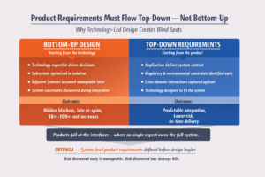
The difference between technology-led design and system-led product requirements is illustrated below.
A Simple—but Costly—Example: EMI and EMC
Electromagnetic Interference (EMI) and Electromagnetic Compatibility (EMC) requirements apply to every commercial and government product.
It is not enough for LiDAR to work as a standalone subsystem.
- The LiDAR must operate in the presence of nearby electronics that can degrade its performance.
- At the same time, the LiDAR itself can interfere with adjacent systems once integrated.
Does the CTO understand EMI/EMC with the same depth they understand LiDAR technology?
Most likely not—and that’s not a failure of competence. It is a limitation of specialization.
Why This Cannot Be Fixed Later
A common assumption is that EMI/EMC issues can be addressed during system integration.
They cannot.
EMI/EMC constraints must be designed into the LiDAR architecture from day one, including:
- grounding strategies
- shielding approaches
- clocking schemes
- power integrity decisions
- layout constraints
Once these requirements are missed:
- fixing them during development costs roughly 10×
- fixing them after production begins costs 100×
At that point, the LiDAR is often designed out entirely due to cost, schedule, and certification risk.
Products Fail at the Interfaces
This failure mode is not unique to EMI/EMC or LiDAR.
It occurs wherever products rely on interactions between domains that no single expert fully owns.
Products fail at the interfaces—where no single expert owns the full system.
Technology teams optimize what they control.
System failures emerge where ownership is unclear.
The Business Consequences
Investors expect products to materialize on time and as promised.
When late-stage requirement gaps surface:
- schedules slip
- costs escalate
- confidence erodes
In most cases, investors will not fund a second attempt to fix foundational requirement errors. The cost and timeline impact often force the technology to be removed from the intended product entirely.
Great technology does not guarantee a viable product.
The Takeaway
Technology expertise does not automatically translate into product correctness.
Without a disciplined, system-level requirements definition process, even the most advanced technology can fail to become a viable product.
Product requirements must be defined top-down, before design begins.
ORTENGA defines system-level product requirements before irreversible design decisions are locked in.
Risk discovered early is manageable.
Risk discovered late destroys ROI.
The World Is Analog. Decisions Are Digital.
How Continuous Physics Becomes Discrete Action
Nature operates in continuous waves. Competitive systems and human decisions operate in discrete states.
Light varies continuously.
Sound pressure flows smoothly.
Temperature drifts gradually.
The physical world is analog.
Yet perception, biological or engineered, resolves into outcomes: detect or ignore, transmit or suppress, classify or reject.
That transition from continuous physics to discrete action defines modern system architecture.
The Analog Origin of All Signals
Every sensor is fundamentally analog.
A microphone produces voltage proportional to sound pressure.
A photodiode generates current proportional to light intensity.
A thermistor varies resistance continuously with temperature.
Nature does not produce binary digits.
Digital systems impose discretization.
Signals are converted using an Analog-to-Digital Converter and processed in digital hardware such as microprocessors, FPGAs, ASICs, or DSP engines.
This decision is architectural.
Why We Convert Analog to Digital
Digitization enables structural properties that analog systems cannot provide at scale.
Noise Behavior and Predictability
Analog systems degrade gradually with noise.
Digital systems exhibit threshold behavior. Above a sufficient Signal-to-Noise Ratio, detection is reliable. Below it, performance collapses sharply.
With coding and forward error correction, digital systems operate predictably at remarkably low SNR levels.
Spectral Efficiency and Capacity
Digital modulation enables higher bits per Hertz and adaptive resource allocation.
Modern communication standards such as:
- 4G
- 5G
exist because digital processing matured enough to scale reliably across millions of users.
Analog systems cannot scale capacity this way.
Security and Integrity
Once digitized, signals can be encrypted. Keys can rotate dynamically. Authentication and integrity checks can be added.
Analog communication cannot provide cryptographic security natively.
Digital systems can.
When Disciplines Mature, Architecture Shifts
Digital signal processing did not dominate simply because it was programmable.
It became practical when mathematics, algorithms, semiconductor density, and hardware architecture matured together.
In 1965, James Cooley and John Tukey introduced the Fast Fourier Transform. The computational complexity of spectral analysis dropped from O(N²) to O(N log N).
That reduction did not immediately create modern communication systems. It marked a maturity milestone.
As semiconductor density increased and parallel multiply-accumulate units became practical, real-time spectral processing became economically feasible. Only then did OFDM, wideband radar processing, and broadband wireless systems become commercially viable.
Architecture shifts when disciplines converge.
A Broader Pattern in Computing
The same pattern appears in quantum computing.
Algorithms developed by:
- Peter Shor
- Lov Grover
demonstrate that new computational models can reduce theoretical complexity for specific classes of problems.
However, until materials science, coherence control, fabrication, and error correction mature simultaneously, quantum systems remain experimental.
Mathematics signals possibility. Engineering maturity determines marketability.
From Continuous Reality to Discrete Decisions
This transition from analog input to digital action can be visualized as a signal boundary.
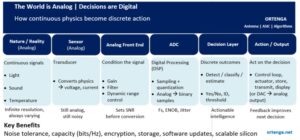
Everything before the ADC is governed by physics.
Everything after it is governed by computation.
The strategic question is not whether to digitize. It is when the digital domain is mature enough to absorb complexity economically.
The Shrinking Analog Boundary
In modern radio and sensing systems, analog is increasingly confined to:
- Antenna
- Air interface
- Low Noise Amplifier
- Power Amplifier
Everything else moves digital.
This architectural shift enabled:
Software-defined radio
Software-defined radio became viable not because software was desirable, but because ADC speed, DSP capability, and semiconductor scaling reached sufficient maturity.
The Strategic Question
The world is analog.
Decisions are digital.
But digital dominance is not automatic.
It emerges when:
- Algorithms scale
- Silicon scales
- Power budgets allow it
- System architecture absorbs it economically
Draw the analog–digital boundary too early and cost explodes.
Draw it too late and flexibility disappears.
Architecture is timing.
ORTENGA Perspective
At ORTENGA, system design begins by asking a disciplined question.
Is the digital domain mature enough to absorb this function at the required power, cost, and schedule?
Defining that boundary correctly determines whether a system becomes market-ready or remains a laboratory exercise.
Physics defines the input.
Multidisciplinary maturity determines whether decisions can be digital at scale.
When Markets Contract, Real Engineering Leadership Emerges
How Architecture Discipline and Technical Investment Define the Next Market Leaders
Economic expansion hides weak strategy.
Economic contraction exposes it.
When revenue slows and markets tighten, leadership teams face a defining choice:
- Protect the quarter
- Or build the next cycle
Only one creates durable advantage.
The Default Reaction: Cut Engineering
In downturns, engineering becomes the fastest visible cost lever.
Headcount reductions improve margins quickly.
R&D programs pause.
Platform upgrades slow.
For companies facing temporary market softness, disciplined cost control may stabilize operations.
But for companies already losing competitiveness, cost reduction does not restore technical leadership. It only improves optics.
If architecture is aging and product economics are misaligned, labor cuts cannot correct structural weakness.
They preserve cash.
They do not create relevance.
The Structural Risk: Confusing Cost with Capability
Some organizations attempt a more aggressive move:
Replace experienced engineers with lower-cost resources.
Quarterly reports improve. Overhead drops.
Yet two risks follow:
- Institutional knowledge disappears — especially in complex systems such as antenna, ASIC, RF, embedded firmware, and algorithms.
- Product architecture remains unchanged.
Labor optimization without architectural evolution does not produce leadership.
It increases the probability of acquisition — not renewal.
What Enduring Technology Leaders Do Differently
Companies that emerge stronger from downturns operate from discipline, not reaction.
They assume competitors will catch up.
They plan for it.
They invest continuously in:
- Architecture reassessment
- Feasibility studies
- Platform migration
- Prototype validation
They do not over-expand during growth cycles.
Therefore, they are positioned to act during contraction.
And when others cut engineering, they selectively hire.
That is leadership.
The Overlooked Lever: Intellectual Property Deployment
Many corporations hold substantial patent portfolios that are underutilized.
In up cycles, these assets often remain dormant.
In down cycles, they become strategic capital.
Leadership asks:
- Which patents apply beyond current product lines?
- Which technologies enable adjacent verticals?
- Which assets can be licensed or divested?
- Where can prior R&D generate alternative revenue?
Engineering leadership includes portfolio visibility.
Not just building new platforms —
But unlocking value from existing ones.
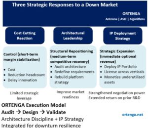
ORTENGA’s Execution Discipline
During economic contraction, structured decision-making matters more than activity.
ORTENGA operates through a three-phase model:
AUDIT
- Product architecture assessment
- Patent portfolio evaluation
- Gap and redundancy identification
DESIGN
- Feature prioritization aligned to business goals
- Cross-application IP strategy
- Monetization pathway definition
VALIDATE
- Technical feasibility confirmation
- Market alignment verification
- Licensing, integration, or deployment execution
This integrated approach allows corporations to:
- Protect margin responsibly
- Re-architect intelligently
- Monetize dormant IP assets
Downturn strategy becomes deliberate — not reactive.
The Strategic Reality
Cost cutting protects the quarter.
Architecture discipline builds the next product cycle.
IP deployment creates strategic optionality.
Companies that combine all three — with structure — emerge stronger.
Economic contraction does not create engineering leadership.
It reveals whether it was there all along.
Cross-Domain Intelligence vs. Pattern Recognition
Why Engineering Breakthroughs Require Model Invention, Not Just Optimization
In 1939, in Systems of Logic Based on Ordinals, Alan Turing distinguished between two kinds of mathematical processes: intuition and ingenuity. He argued that machines are capable of mathematical ingenuity — disciplined execution of formal rules — but not mathematical intuition.
He did not mean mysticism.
Ingenuity operates within a defined formal system.
Intuition steps outside the system and extends it.
Modern AI systems are extraordinary engines of ingenuity. They search, optimize, classify, predict, and synthesize at scale. But Turing’s distinction remains deeply relevant: operating within a model is fundamentally different from redefining the model itself.
In engineering, this difference is not philosophical. It determines cost, architecture, and return.
Pattern recognition optimizes inside a model.
Cross-domain intelligence invents the model.
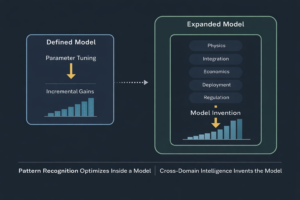
The Difference That Changes Outcomes
Pattern recognition improves performance once objectives and constraints are correctly specified. It extracts regularities and refines outputs inside a defined abstraction.
Cross-domain intelligence is different. It questions whether the abstraction itself is complete. It recognizes when constraints are underweighted, when objectives are misaligned, or when the governing structure belongs to a different domain altogether.
If you can improve performance by tuning parameters, you are inside the model.
If performance only improves after redefining objectives or constraints, the model needed invention.
Optimization is powerful.
But only after the governing abstraction is correct.
When Competitive Pressure Compresses Model Validation
In rapidly evolving technology markets, later entrants often face incumbents that have already demonstrated large-scale deployment.
Under competitive pressure, engineering focus naturally converges on closing visible gaps:
- Deployment cadence
- Hardware cost reduction
- Core performance metrics
- Manufacturing scale
These priorities are rational.
But competitive acceleration can compress time allocated for validating the full governing abstraction — disciplined alignment of:
- Deployment environment variability
- Power and thermal margins
- Manufacturing elasticity
- Regulatory diversity
- Cross-market adaptability
In many large-scale infrastructure programs, early optimization concentrates on the primary technical objective — for example, throughput or link budget.
Later iterations often reflect expanded recognition of constraints that were underweighted in the original model.
The system may function correctly.
The abstraction evolves.
However, abstraction maturation after deployment is materially more expensive than abstraction validation before deployment.
Pattern recognition improves performance inside a defined model.
Cross-domain intelligence expands the model before scale.
When Operational Reality Expands the Constraint Set
A second pattern emerges when systems are deployed in contested or adversarial environments.
Performance metrics that dominate early design phases — such as speed, cost per unit, or efficiency — may give way to new governing constraints:
- Resilience under interference
- Adaptive response to adversarial conditions
- Secure update mechanisms
- Robust coordination across distributed nodes
In such environments, resilience is no longer a feature.
It becomes an architectural prerequisite.
The original model may have optimized performance in nominal conditions.
Operational deployment expands the constraint set.
The technology may remain sound.
But the governing abstraction must evolve.
Optimization inside a performance-centric model cannot fully address a resilience-centric reality — until the model itself is redefined.
The Structural Lesson
In both scenarios:
- The engineering is competent.
- The optimization is effective.
- The constraint set evolves.
When abstraction expands after deployment, revisions become reactive and expensive.
When abstraction expands before deployment, revisions become strategic and controlled.
The difference is not technical skill.
It is when the governing model is invented.
The Economic Parallel: When Model Confinement Destroys Return
The same dynamic applies to venture-backed deep technology companies.
Many startups do not struggle because their core technology lacks merit. They struggle because their governing business abstraction is too narrow.
They optimize inside a single product definition:
- One vertical
- One market assumption
- One deployment model
- One performance metric
Engineering improves.
Milestones are met.
Capital is deployed.
Yet adoption stalls.
The technical foundation may be strong.
The model is incomplete.
A sensing platform designed for one vertical may apply to another.
A signal processing architecture optimized for one use case may unlock value in adjacent markets.
An inference accelerator built for a single application may enable multiple sectors.
If cross-product links are not identified early, capital concentrates inside a confined abstraction.
When that abstraction underperforms commercially, the portfolio appears distressed.
The technology was not necessarily wrong.
The model was too narrow.
Cross-domain intelligence converts technical assets into optionality.
Optionality reduces risk.
Optionality increases return.
The ORTENGA Engineering Risk and RoI Blueprint
Engineering breakthroughs do not begin with optimization. They begin with reframing.
Before parameters are tuned, before algorithms are accelerated, before hardware is committed, the governing abstraction must be correct. Constraints must reflect physics, integration, computation, deployment, and economics.
Pattern recognition improves performance inside a model.
Cross-domain intelligence invents the model.
At ORTENGA, this is formalized as the ORTENGA Engineering Risk and RoI Blueprint.
Audit
Identify where assumptions, constraints, and objectives are misaligned with system reality. Surface hidden governing constraints. Map cross-product and cross-vertical applications embedded within the same technical foundation — especially within underutilized patent portfolios.
Design
Reconstruct the governing abstraction layer so physics, architecture, computation, and economics align before capital scales.
Validate
Stress-test the reframed model against deployment, manufacturability, integration, and capital constraints before reinvestment or expansion.
Optimization without model invention compounds exposure.
Model invention before optimization compounds return.
If you are deploying capital into deep technology, derisk the abstraction before you scale the optimization.
Engage ORTENGA to audit, reframe, and validate your model before it compounds exposure.
First to Define, First to Win
Why System Architecture and Product Vision Determine High-Tech ROI
High-tech markets do not reward imitation. They reward definition.
The companies that generate durable return on investment are not the fastest followers. They are the ones that define system architecture, shape user expectations, and anticipate requirements before the market articulates them.
Once traction becomes visible, capital floods in. Competitors multiply. Feature sets converge. Pricing compresses.
Return on investment declines as competitive density increases.
The issue is not whether demand exists.
The issue is whether structural advantage still does.
The ROI Compression Effect
Competitive entry follows a predictable economic pattern.
- The market creator defines architecture and captures premium economics.
- The second entrant reduces margins but still earns meaningful return.
- By the third and fourth competitors, differentiation narrows and price dominates.
- Beyond that point, capital efficiency deteriorates sharply.
Participation does not guarantee return.
Density determines economics.
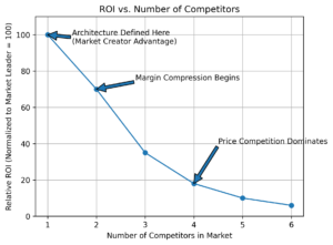
Each coordinate represents expected capital efficiency at a given number of viable competitors. The curve reflects structural compression.
Margin durability is highest when architecture is first defined — and declines as imitation increases.
Architecture Leadership vs. Reactive Entry
Speed alone does not create durable ROI. Structural positioning does.
An architecture leader:
- Defines system boundaries early
- Embeds monetizable differentiation
- Scales before competitive density increases
- Establishes pricing benchmarks
A reactive entrant:
- Enters after validation is visible
- Competes within predefined architecture
- Faces immediate pricing pressure
- Operates under compressed economics from inception
The financial trajectories diverge accordingly.
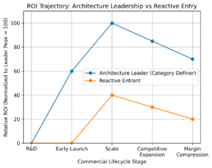
The architecture leader captures peak ROI during scale — before density erodes pricing power.
Reactive entrants typically enter during expansion, when structural economics are already tightening.
By the time opportunity appears obvious, advantage has often already been allocated.
Why Markets Are Misread
Visible demand is frequently mistaken for attractive economics.
However, once a market becomes visibly compelling:
- Architecture has already been defined
- Ecosystems are consolidating
- Switching costs are forming
- Pricing anchors are established
Late participation shifts the game from value creation to margin defense.
Execution excellence cannot fully compensate for structural disadvantage.
The Discipline Behind Durable ROI
Sustainable returns begin before development.
Audit
Identify structural advantage before selecting architecture.
- Is the product definition defensible?
- Does it enable cross-product reuse?
- Is differentiation structural or cosmetic?
- What happens to ROI at competitor #4?
- Is the opportunity expandable across portfolios?
Audit determines whether durable advantage is even possible.
Architecture is not chosen here.
Structural leverage is identified here.
Design
Select system architecture only after structural advantage is confirmed.
- Does the architecture enable scalable differentiation?
- Does it preserve pricing power under density?
- Does it support platform extension and reuse?
- Is cost structure aligned with competitive reality?
Design translates strategic leverage into technical structure.
Validate
Ensure economics survive real-world pressure.
- Stress-test ROI under competitor expansion
- Confirm cost resilience under margin compression
- Verify roadmap durability beyond launch
Validation protects capital from optimism bias.
Executive Insight
Entering a visible market is easy.
Defining a structurally advantaged position is difficult.
Audit determines whether durable advantage exists.
Design operationalizes it through architecture.
Validation confirms that returns survive competition.
Product definition precedes profitability.
System architecture operationalizes advantage.
Return on investment is protected through disciplined system architecture and product definitions.
The ORTENGA Perspective
ORTENGA works with leadership teams before capital is committed — auditing product definition, identifying structural leverage, selecting defensible architecture, and validating economics under competitive density. In high-tech industries, ROI is not recovered through execution speed alone — it is protected through disciplined system architecture and product definitions.
From Concept to Customer Return: Why Weak Product Definitions Inflate Cost, Slip Schedules, and Undermine RoI
How Missing Audit Discipline and Unjustified Specifications Create the Same Root Cause at Every Phase of Product Development
Executive Opening
Most product failures do not begin in validation.
They do not begin in manufacturing.
They do not even begin in design.
They begin in definition.
When product concepts are not audited against real market needs, system-level constraints, and manufacturability realities, assumptions become embedded in architecture. When specifications are not economically justified, trade-offs become distorted. By the time validation confirms compliance, structural misalignment has already been engineered into the product.
The failure only becomes visible when customers return it.
At that moment, leadership sees the symptom:
- Cost inflation
- Schedule slip
- Margin erosion
- RoI collapse
But the root cause has been present since the earliest phase.
What changes across development stages is not the cause.
It is the failure signature.
The Escalation Pattern Across the Lifecycle
Across the lifecycle, weak definitions reveal themselves differently.
Concept Phase — Undefined Assumptions
- Differentiation not clearly articulated
- Performance targets derived from competitors rather than strategy
- No quantified trade-offs
- No system-level audit
Correction cost: 1×
Design Phase — Distorted Trade-Offs
- Arbitrarily tightened specifications
- Overengineering in non-differentiating areas
- Under-protection of margin-critical parameters
- Cross-domain friction across antenna, ASIC, algorithm, hardware, firmware, and software
Design locks in assumptions.
Capital becomes committed.
Correction cost: 10×
Validation Phase — False Confidence
- Pass/fail criteria misaligned with field reality
- Guard bands missing in customer-critical areas
- Lab compliance without real-world robustness
Validation confirms what was defined.
If definitions were flawed, validation institutionalizes the flaw.
Correction cost: 10×–100×
Post-Launch — Customer Return
- Field variability exposes tight margins
- Product meets minimum specification but fails expectations
- Engineering teams diverted to containment
- Roadmaps delayed
Correction cost: 100×
At this stage, the issue is structural.
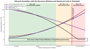
The opportunity window is RoI-index driven.
After structural lock-in, recovery no longer restores return — it only limits damage.
The Hidden Multiplier: Engineering Bandwidth
Weak product definition does more than inflate direct cost.
It consumes engineering capital.
Highly skilled teams spend months:
- Reconciling ambiguous requirements
- Retrofitting margins
- Redefining validation criteria
- Debugging preventable edge cases
- Reworking architecture under schedule pressure
This is not engineering complexity.
It is preventable distraction.
Innovation slows.
Time-to-market slips.
RoI erodes long before customers notice.
Why RoI Collapses Before Margin Disappears
Margin erosion is gradual.
RoI collapse is structural.
A product can still generate revenue while:
- Capital has already been over-committed
- Schedule delays have destroyed first-mover advantage
- Engineering diversion has postponed next-generation programs
By the time RoI drops below a structural threshold, correction becomes economically infeasible.
Not because the product cannot function.
But because the investment thesis no longer holds.
The Common Root Cause
Across all phases:
- Missing early audit discipline
- Specifications not economically justified
- No traceability from business goals to architecture
- Validation misaligned with customer value
Different symptoms.
Same origin.
Weak product definition.
The Preventable Discipline
The solution is not more testing.
It is earlier clarity.
Audit
Interrogate product concepts against market reality, system constraints, manufacturability, and margin strategy before architecture begins.
Design
Translate justified requirements into disciplined cross-domain trade-offs aligned with business objectives.
Validate
Confirm real-world robustness and economic viability — not just checklist compliance.
Final Executive Insight
When cost inflation, schedule slip, and customer returns appear, the structural decisions that caused them were made months earlier.
Leaders who recognize this pattern understand:
If RoI collapse appears after launch, the root cause likely began before design.
Disciplined product definitions protect capital.
Justified specifications protect architecture.
Aligned validation protects market trust.
Partner with ORTENGA to Audit, Design, and Validate what truly matters — before each phase reveals the same preventable root cause.
Wireless Power Transfer: It’s Not About RF — It’s About Wavelength Discipline
The viability of wireless power transfer is determined long before the first RF simulation is run.
It is determined by commercial constraints.
A scalable product must satisfy real boundaries:
- ~1 W average delivered RF power
- ≤10 W average transmitted power
- Practical transmit aperture (e.g., 10 cm × 10 cm)
- Device-constrained receive antenna geometry
- Deployment ranges aligned with actual use cases
These are not extreme assumptions.
They are disciplined product filters.
Once these constraints are defined, physics narrows the solution space dramatically.
Aperture and Wavelength Together Define the Energy Envelope
In real products, antenna gain is not an abstract number.
Both transmitter and receiver are constrained by physical geometry.
- The transmitter has finite aperture area.
- The receiver is embedded in a device whose size limits its effective antenna area.
For geometry-constrained antennas:
- Larger physical aperture increases energy concentration at range.
- Higher frequency increases gain for the same physical size.
- Beamwidth narrows as wavelength decreases.
- Alignment tolerance shrinks accordingly.
Physical aperture constraints define the achievable power–distance envelope.
Wavelength determines how that envelope is shaped — and how difficult it is to control.
Higher frequency improves spatial concentration.
Lower frequency improves tolerance and robustness.
Wavelength selection is therefore not an RF optimization problem.
It is a geometry-and-control trade.
Three Wavelength Anchors
Assume a 10 cm transmit aperture.
Beamwidth scales approximately with:
HPBW ≈ λ/D
(Exact constants vary with illumination, but λ/D scaling dominates.)
 This produces three practical regimes.
~10 GHz (≈ 3 cm) — Broad Energy Zone
- Beamwidth ~15° class
- Alignment tolerant
- Modest tracking requirements
- Significant spatial spillover
This behaves like zone illumination. It supports robust short-to-moderate range delivery, but makes tight spatial containment and multi-device isolation more difficult.
~30 GHz (≈ 1 cm) — Directed Delivery
- Beamwidth ~5°
- Controlled spatial focus
- Moderate steering and tracking requirements
This regime balances energy concentration with manageable control complexity. For constrained apertures and disciplined power budgets, it represents a practical architectural balance.
~100 GHz (≈ 3 mm) — Precision Targeting
- Beamwidth ~1.5°
- High spatial confinement
- Minimal spillover
This enables precise energy delivery and strong device isolation.
But the system now changes character.
Beamwidth Shrinks → Control Complexity Explodes
As beamwidth narrows, wireless power transitions from an RF hardware challenge to a closed-loop control problem.
With narrow beams:
- Small pointing errors cause multi-dB loss
- Device motion interrupts alignment
- Beam scanning must accelerate
- Feedback channels become necessary
- Calibration precision becomes critical
A 15° beam tolerates drift.
A 1.5° beam demands active tracking.
Under realistic commercial constraints — 1 W average delivery, ≤10 W average transmission, practical antenna geometries — the dominant risk shifts from RF component capability to aperture geometry, beam control, and system architecture.
RF hardware is necessary.
Control architecture determines robustness.
Environmental Loss Is Not Uniform Across Wavelength
The discussion above assumes free-space propagation.
In practice, atmospheric absorption varies with frequency:
- Below ~20 GHz, absorption is typically negligible over short indoor ranges.
- Around 60 GHz, oxygen absorption becomes measurable.
- At higher millimeter-wave bands, absorption and rain fade increase.
For short-range indoor scenarios (~10 m), these losses are usually secondary to geometric spreading and alignment.
For outdoor or extended-range deployments, wavelength-dependent absorption becomes part of the architectural decision.
Higher frequency improves spatial confinement — but increases environmental sensitivity.
Again, wavelength discipline matters.
The Real Product Equation
A viable wireless power product must co-design:
- Transmit aperture geometry
- Device receive geometry
- Wavelength class
- Beamwidth
- Tracking tolerance
- Duty-cycle strategy
- Deployment environment
When those variables are aligned, wireless power becomes practical.
When wavelength is selected in isolation, complexity grows faster than performance.
The ORTENGA Perspective
At ORTENGA, product definition begins with constraints:
- Delivered power requirement
- Acceptable transmission ratio
- Physical aperture limits
- Deployment geometry
- Control tolerance
- Environmental assumptions
From those constraints, wavelength is selected deliberately.
Physical geometry defines the power–distance envelope.
Wavelength defines beam behavior.
Beam behavior defines control complexity.
Control complexity defines product viability.
Wireless power succeeds when those layers are co-designed.
It fails when wavelength is treated as an RF afterthought.
Turn-Key or Disruptive? The Strategic Architecture Decision That Determines Market Leadership
How COTS Integration Reduces Risk — and Why Custom Architecture Defines Long-Term Defensibility
Most companies believe they are making a product decision.
In reality, they are making a capital allocation decision disguised as engineering.
Turn-key models optimize speed.
Custom architecture builds defensibility.
The difference determines whether you compete on release cycles —
or redefine markets for years.
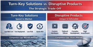
Turn-key strategies rely on:
- Commercial Off-The-Shelf (COTS) hardware
- Firmware/software differentiation
- Integration as the primary value layer
Advantages
- Lower upfront R&D cost
- Faster time to market
- Reduced execution uncertainty
- Faster revenue capture
Structural Limitation
If your core hardware is available to everyone, your moat is measured in firmware cycles.
Your competitor is months behind you — not years.
Turn-key optimizes speed.
It does not create architectural defensibility.
Disruptive (Custom Architecture Model)
Disruptive products require:
- Custom hardware architecture
- Algorithm + silicon co-design
- RF + digital integration
- Power, thermal, and cost-curve ownership
Advantages
- Multi-year competitive separation
- Cost structure control
- Hard-to-replicate system depth
Risks
- Higher capital exposure
- Longer timelines
- Greater integration complexity
If executed well: competitors cannot copy quickly.
If executed poorly: capital evaporates.
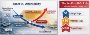
The real difference becomes visible over time.
Turn-Key:
- High initial speed
- Low long-term defensibility
Disruptive:
- Slower initial ramp
- Strong long-term moat
The crossover point determines market leadership.
This is not a feature decision.
It is an architecture decision.
Note the Blind Spot Risk Zone in the visual —
this is where companies underestimate integration complexity.
The 1× → 10× → 100× Rule

A universal engineering principle:
- $1 at architecture stage
- $10 at prototype
- $100 at production
Errors discovered late become balance-sheet events.
This rule applies to both models —
but custom architecture magnifies the consequences of poor early decisions.
Disruption fails when architecture discipline is weak.
Turn-key fails when differentiation is shallow.
The protection mechanism is structured execution.
Phase 1 — Audit
Define before building.
- Real-world use cases
- Operational envelope
- Ecosystem constraints
- RoI sensitivity
- Architectural blind spots
Skipping this phase converts engineering into speculation.
Phase 2 — Design
Architect before implementing.
- Lock system interfaces early
- Align RF + Digital + Algorithm stack
- Stress-test manufacturability
- Prevent hidden integration risks
Design is where risk is either removed — or embedded.
Phase 3 — Implement & Validate
Implementation and validation are inseparable.
Design Implementation
- Hardware realization
- Firmware/software integration
- Silicon and RF maturity
- System integration closure
Validation Against Audit-Defined Use Cases
- Real-world operating scenarios
- Environmental stress
- Power and thermal verification
- Ecosystem interoperability
- Manufacturing repeatability
Validation is not “does it work in the lab?”
It is:
Does it perform under the exact use cases defined during Audit?
If not, the 10×–100× rule activates.
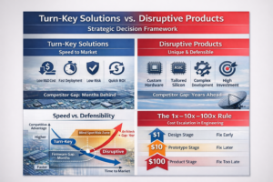
Strategic Conclusion
Turn-Key reduces early risk and accelerates entry.
Custom architecture increases early complexity —
but defines long-term market power.
The mistake is not choosing one or the other.
The mistake is choosing without architectural clarity.
Market leadership is rarely lost at launch.
It is lost at architecture definition.
Technology Is Not a Product
The System Discipline That Protects Capital
A working technology does not make a product.
A successful demo does not create a business.
And physics validation does not guarantee return on capital.
In high-tech startups, investment often follows technical proof. The prototype works. Performance is measurable. The team demonstrates capability.
But markets do not reward capability.
They reward systems that solve complete problems — reliably, repeatably, and economically.
Most high-tech failures are not engineering failures.
They are definition failures.
An Early Lesson in System Discipline
Early in my career, I was asked to draft requirements for a radio front control system for a 2G base station integrating a superconducting cavity pre-selector filter.
I had studied architectures from companies such as Motorola, Ericsson, and Nokia. I understood radio front-end systems.
But when writing the requirements, I unconsciously shaped them around what we were capable of building.
That is the path of least resistance.
A senior stakeholder — a former Motorola system engineer — stopped me.
His instruction was simple:
Define everything the system requires — whether we can build it or not.
Capabilities follow requirements. Not the other way around.
That distinction changed how I approach every design engagement.
The Pattern Behind Capital Destruction
When requirements are shaped by internal capability:
- Critical features are excluded
- Interfaces remain ambiguous
- Performance envelopes are assumed
- Integration risks appear late
- Cost models collapse during implementation
- Validation becomes damage control
The team still says:
“But the technology works.”
Yes.
But the system was never independently defined.
And capital was committed before architectural discipline was enforced.
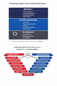
The Discipline That Protects Capital
I frame system execution in three phases:
Audit → Design → Validate
Audit defines intent.
Design defines structure.
Validation proves economic viability.
- Audit (Intent & Economic Definition)
- What problem must be solved?
- What performance envelope is mandatory?
- What operational conditions define success?
- What interfaces are required?
- What deployment realities constrain the system?
- What will the market pay for?
At this stage, internal capability is irrelevant.
Audit defines intent — independent of ego, habit, or comfort.
- Design (Architectural Decomposition)
Design translates audited intent into structure.
- Hardware architecture
- Firmware control logic
- Software framework
- Algorithm selection
- HW / FW / SW interface definition
- Resource and performance budgets
- Waveform or protocol requirements derived from use cases
Every design element must trace back to an audited requirement.
If it does not trace — it does not belong.
- Validate (Implementation & Proof)
Validation is not testing at the end.
It includes full implementation and verification:
- Hardware implementation
- Firmware implementation
- Software implementation
- Cross-domain integration
- System-level verification
- Use-case execution under real constraints
- Margin and cost confirmation
Validation proves that what was defined in Audit has been realized through Design and implemented correctly across HW / FW / SW.
If audit assumptions are not implemented and verified:
You do not have a product platform.
You have a funded prototype.
The 75% Result
When we rewrote the requirements independently of our internal constraints, clarity emerged.
The final control system reduced cost by approximately 75% relative to the alternative solution under development.
Not because of better technology.
Because of better definition.
The Hard Truth for Founders and Investors
A prototype proves feasibility.
A product requires:
- Complete system definition
- Traceable architecture
- Disciplined implementation
- Verified economic viability
Technology excites investors.
System discipline protects them.
At ORTENGA, we engage before architecture is frozen.
We ensure:
- Requirements are complete
- Assumptions are challenged
- Interfaces are defined
- Performance is justified
- Design elements are traceable
- Implementation is verifiable
Because:
Technology is not a product.
System definition turns innovation into return on investment.
The Requirement That Never Got Written
How Role Compression Undermines Product Strategy
Most Product Failures Begin in Governance
Most product failures do not begin in engineering.
They begin in governance.
In many organizations, the same executive is responsible for defining product requirements and delivering the product to market. On paper, this appears efficient.
In practice, it compresses two structurally different responsibilities into one role:
- Defining what must be true to win
- Delivering what is feasible within time and budget
This is role compression.
And it quietly reshapes product strategy long before a single line of code is written.
When definition and delivery live in the same seat, execution pressure begins influencing what gets defined.
That is where the most important requirement is often lost.
The Structural Conflict
Product definition demands clarity about:
- What the market truly values
- What differentiates the product
- What is required to win — not merely participate
Product delivery demands:
- Schedule discipline
- Budget adherence
- Resource optimization
- Risk containment
These objectives are not identical.
When one executive carries both mandates, difficult requirements are unconsciously filtered out.
Not because they are impossible.
But because they complicate execution.
What Gets Missed
The requirements most likely to disappear share predictable characteristics:
- Technically sophisticated
- Cross-domain (HW / FW / SW / algorithms)
- Architecturally consequential
- Challenging but achievable
- Central to differentiation
They are rarely infeasible.
They are simply uncomfortable.
And uncomfortable requirements are the first to go.
The Market Does Not Care About Internal Comfort
A product may:
- Meet documented specifications
- Pass internal reviews
- Launch on schedule
- Satisfy baseline functionality
Yet still struggle.
Because the market valued what was never written down.
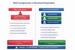
The Discipline That Prevents This
This is precisely why product development must follow structural separation:
Audit defines intent.
Design defines structure.
Validation proves economic viability.
Audit Phase
- What does the market value disproportionately?
- What are the make-or-break differentiators?
- What must be true to win?
Audit must be independent of delivery pressure.
Design Phase
- Technical decomposition across HW / FW / SW
- Clear subsystem interfaces
- Traceability from requirement to architecture
Design translates intent into structure.
Validation Phase
- Verify differentiating requirements are met
- Confirm architectural assumptions
- Demonstrate economic viability
- Validate alignment with original intent
If Audit assumptions are not traceable through Design and proven in Validation:
You do not have product strategy.
You have coordinated execution.
The Hidden Cost of Role Compression
When definition is compromised:
- Engineering optimizes secondary features
- Architectural decisions become reactive
- Competitors capture premium positioning
- Margin compresses
- RoI declines
- Recovery becomes exponentially harder post-launch
The organization does not fail because engineers lack capability.
It fails because the critical requirement was never institutionalized.
The Leadership Question
The real question is not:
“Can engineering build this?”
The real question is:
“Did we structurally protect the definition process from delivery pressure?”
Because once written, a requirement demands architecture.
Once architected, it demands resources.
Once resourced, it demands discipline.
That is where differentiation lives.
And that is where product strategy is either preserved — or quietly compromised.
ORTENGA Perspective
Protect the Definition Phase Before Capital Is Committed
Role compression is not a leadership flaw — it is a structural risk.
When product definition and delivery accountability live in the same structure, differentiation is quietly exposed to execution pressure.
Independent audit restores discipline between intent and execution.
ORTENGA partners with executive teams to independently assess product definitions before design resources are committed — identifying missing make-or-break requirements, cross-domain blind spots, and structural risks to differentiation.
Because once architecture is funded, correction becomes expensive.
Before committing capital — validate the definition.
When Gain Becomes Scarce, Wavelength Forces Antenna–Device Co-Residence
How Frequency Simultaneously Forces Semiconductor Down-Selection and Antenna Proximity
As operating frequency increases, semiconductor devices approach intrinsic limits defined by fT and fmax. Maximum Stable Gain (MSG) decreases monotonically with frequency — approximately 6 dB per octave as operation approaches the boundary of a given technology.
This behavior is continuous and physics-driven. It reflects the diminishing ability of a device to provide usable power gain at higher frequencies.
As available gain decreases, semiconductor platform selection becomes increasingly constrained. CMOS becomes limited first. SiGe extends the usable range. III–V compound technologies extend it further.
This defines the available gain envelope at a target frequency.
At the same time, frequency reduces wavelength, and electromagnetic scale begins to dominate physical geometry.
Interconnect lengths that were electrically negligible at lower frequencies become significant fractions of wavelength. Conductor and dielectric losses increase with frequency. Transitions, vias, bond wires, and impedance discontinuities introduce measurable attenuation.
Routing is no longer electrically small.
These two effects are driven by the same variable — frequency — but they manifest differently:
- Frequency reduces available semiconductor gain.
- Frequency reduces wavelength, increasing routing sensitivity.
Their interaction reshapes radio design.
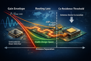
Figure 1 — Increasing frequency simultaneously reduces available device gain and increases routing attenuation. The viable design space narrows until antenna–device co-residence becomes necessary.
Device Gain and System Power
As device gain decreases with increasing frequency, achievable and efficiently deliverable RF output power becomes constrained. Power-added efficiency declines as operation approaches intrinsic device limits. Breakdown voltage and current density restrict achievable voltage swing and output power per device.
Thermal density further limits practical amplification. Even when electrical gain exists, heat dissipation capability bounds usable output power.
At frequencies above 100 GHz, excess power margin is limited.
Each millimeter of transmission line introduces incremental attenuation. Routing loss subtracts directly from deliverable RF power before it reaches the antenna. In this regime, even small fractions of a decibel meaningfully reduce radiated power and EIRP.
When Separation Consumes Power
Historically, radio architecture allowed physical separation:
RFIC → matching network → transmission line → antenna
At lower frequencies, routing loss represented a small fraction of available gain and output power.
At higher frequencies, this separation becomes progressively less viable.
As device gain decreases and routing attenuation increases, antenna placement becomes a power-budget consideration rather than a packaging preference.
When routing attenuation meaningfully reduces deliverable RF power, antenna–device co-residence emerges as a practical necessity.
The antenna must migrate toward the active front end — into the package substrate, onto the same laminate, or within immediate proximity of the semiconductor — to preserve limited output power.
This shift is not abrupt, nor is it stylistic.
It is the deterministic outcome of frequency acting simultaneously on semiconductor gain and electromagnetic scale.
Multidisciplinary Engineering at the Feasibility Boundary
At higher operating frequencies, product viability is no longer determined by a single discipline.
Semiconductor gain behavior, output power limits, thermal constraints, routing attenuation, electromagnetic geometry, and antenna topology interact continuously. Evaluating any one in isolation is insufficient.
Feasibility above 100 GHz requires coordinated assessment across:
- Semiconductor device limits (MSG behavior, proximity to fT / fmax)
- Achievable output power under efficiency and thermal constraints
- Routing attenuation and transition losses
- Antenna placement relative to electromagnetic scale
- System-level power budgeting and EIRP requirements
These constraints are monotonic and physics-driven. Their combined effect narrows design margin as frequency increases.
ORTENGA engages at this multidisciplinary boundary — where semiconductor physics, electromagnetic scale, antenna engineering, and system-level power constraints must be evaluated together before architecture is frozen.
Through structured engineering Statements of Work, ORTENGA assesses whether a target frequency, semiconductor platform, and antenna strategy are physically, thermally, and electromagnetically viable before significant capital commitment.
When gain becomes scarce and routing consumes power, engineering rigor — not optimism — determines whether ambition translates into viable product or avoidable risk.
System Before ASIC
Why Architecture Defines the Economics of Radar and Wireless Platforms
“In radar and wireless systems, performance is not determined by the chip you select — it is bounded by the architecture you define. And architecture is the technical expression of product intent.”
Architecture is where product conception becomes engineering reality.
In complex radar and wireless platforms, two distinct failure modes repeatedly appear:
Misalignment is one failure mode.
ASIC-first thinking is another.
When you start from available semiconductor devices instead of defined product intent, architecture becomes reactive — and performance boundaries become accidental.
And here is the critical systems insight:
ASIC selection exposes architectural mistakes — it rarely creates them.
By the time an ASIC is selected, architectural commitments have already constrained bandwidth, dynamic range, timing stability, power budgets, and processing resources. The semiconductor device simply makes those constraints visible.
The distinction between system-driven architecture and ASIC-driven design is structural, not cosmetic:
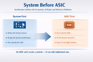
Figure 1 — System definition must precede ASIC commitment.
To understand why architecture must precede ASIC selection, we must examine the three interdependent domains that define every radar and wireless platform.
The Three Architectural Domains
Every radar and wireless system is bounded by three tightly coupled domains:
- Radio Systems Architecture
- Waveform Requirements (Communications vs. Radar)
- Digital Signal Processing (DSP)
These domains define the performance envelope long before hardware is finalized.
If they are aligned with product intent, the ASIC becomes an implementation tool.
If they are misaligned, the ASIC becomes a constraint amplifier.
- Radio Systems Architecture
Radio architecture operates within the air interface — it does not control propagation, it must respond to it.
The propagation environment introduces attenuation, multipath, fading, interference, and other impairments that cannot be engineered away. Architecture determines how robustly the system survives those realities by:
- Allocating link margin
- Managing transmit power
- Selecting antenna topology and gain
- Preserving linearity
- Controlling noise figure
- Managing dynamic range
Its function is to preserve signal integrity before digitization.
But architecture must also avoid becoming a source of impairment itself.
DSP can compensate for impairments — but it cannot reverse irreversible corruption introduced by poor architectural choices.
Excessive nonlinearity, insufficient bandwidth, phase noise, clipping, or coarse quantization permanently degrade recoverable information. Once information is irreversibly corrupted, it cannot be recreated downstream.
Architecture determines the quality of information that enters the digital domain.
- Waveform Requirements: Communications vs. Radar
Waveform design exists in both communications and radar systems — but the requirements shaping those waveforms are fundamentally different.
In Radio Communications
Waveform requirements are driven by:
- Data throughput
- Spectral efficiency
- Required Eb/N₀
- Bit error rate targets
- Latency constraints
- Spectrum coexistence
The objective is reliable information transfer.
Communications systems are governed by information theory and capacity limits.
In Radar Systems
Waveform requirements are driven by detectability and resolution.
In radar:
- Range resolution dictates bandwidth
- Velocity resolution dictates timing and coherence
Range resolution improves with increased bandwidth.
Velocity resolution improves with longer coherent processing time.
These are not DSP optimizations — they are architectural commitments driven by product intent and the characteristics of the targets of interest.
Bandwidth, coherence stability, phase noise, and dynamic range are architectural decisions — not software adjustments.
Communications is governed by information theory.
Radar is governed by detection and estimation theory.
In both domains:
Waveform requirements must be derived from product intent — not inherited from available semiconductor solutions.
- Digital Signal Processing (DSP)
DSP is where architecture and waveform theory are executed.
It implements algorithms necessary to:
- Mitigate propagation and hardware impairments
- Extract data (communications)
- Detect and estimate targets (radar)
In Communications Systems
DSP performs synchronization, equalization, demodulation, and decoding within preserved SNR and distortion limits.
In Radar Systems
DSP performs range processing, Doppler processing, coherent integration, detection, and tracking within available bandwidth and phase stability constraints.
DSP can optimize within defined boundaries —
it cannot expand boundaries that architecture has already constrained.
DSP executes architecture; it does not redefine it.
The Architectural Consequence
By the time an ASIC is selected, three commitments have already been made:
- The radio architecture has defined what signal integrity can be preserved.
- The waveform has defined what performance must be achieved.
- The DSP architecture has defined what processing resources are required.
If those commitments were not derived from product intent and target characteristics, the system will eventually expose the misalignment.
That exposure may appear as:
- Insufficient resolution
- Inadequate link margin
- Excess processing load
- Thermal instability
- Manufacturability challenges
- Cost overruns
At that stage, the semiconductor device is often blamed.
But:
ASIC selection exposes architectural mistakes — it rarely creates them.
System Before ASIC
A defensible radar or wireless platform begins with:
- Clearly defined product intent
- Explicit performance requirements
- Architectural commitments aligned with physics and theory
- Semiconductor implementation that supports — not dictates — those commitments
Because semiconductor devices are implementation tools.
They are not system architects.
Architecture defines what is possible.
The ASIC reveals whether that definition was sound.
How ORTENGA Supports ASIC Startups
ORTENGA helps semiconductor and ASIC startups build system-level knowledge before committing to architecture.
We work with founders and engineering teams to:
- Identify target markets and application domains
- Translate product intent into measurable system requirements
- Define architectural constraints before committing to semiconductor design
- Align ASIC specifications with real-world use cases and system-level needs
An ASIC cannot be defined correctly without system context.
And system context does not begin with competitor benchmarking.
Designing an ASIC solely around what already exists in the market — even with incremental performance improvements — rarely creates durable differentiation. At best, it may gain limited traction as a second- or third-tier solution, often under margin pressure.
Sustainable market traction requires architectural alignment with a clearly defined system problem.
An ASIC is defined by how precisely it solves a validated system-level need.
The Cost of Certainty
Why Sample Size Is a Business Decision, Not Just a Statistical One
Every product that reaches production carries an assumption.
An assumption about the defect escape rate beyond final test screening.
An assumption about how many of those escapes will return as RMA.
An assumption about what that will cost the business — in debug, root-cause analysis, replacement, and reshipping known-good devices.
Those assumptions are embedded in:
- Unit cost models
- Margin targets
- Field service budgets
- Investor expectations
Yet one fundamental question is often treated as a statistical afterthought:
How many units must be tested to justify those assumptions?
Because here is the uncomfortable truth:
If the statistical evidence cannot defend these assumptions, the margin model is speculation.
Certainty Has a Price
Confidence is not free.
Every additional unit tested buys statistical certainty.
Every incremental point of confidence consumes capital, time, and engineering bandwidth.
Lower target DPM requires disproportionately larger sample size.
Higher confidence requires disproportionately larger sample size.
Certainty scales inversely with defect rate.
And validation cost scales accordingly.
DPM vs Statistical Sample Size (95% Confidence, Zero Failures)
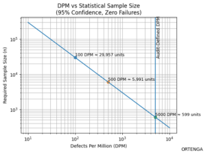
As target DPM decreases, required statistical sample size increases nonlinearly. Certainty improves — but so does validation cost.
DPM Must Be Defined in Audit — Not in Validation
DPM is not discovered during validation.
It must be defined during product conception — when RoI is forecasted and margin tolerance is calculated.
Validation does not choose defect targets.
It verifies whether the business assumptions were realistic.
Numeric Example: DPM Derived from RoI
Assume during Audit:
- Annual shipment volume: 500,000 units
- Fully burdened RMA cost: $180 per return
- Maximum acceptable annual field-failure cost: $450,000
From these assumptions:
- Allowable annual returns = 2,500 units
- Escape rate = 0.5%
- Required performance = ≤ 5,000 DPM beyond final test screening
That single business constraint immediately defines the scale of statistical validation required.
The RoI model determines the defect tolerance.
The defect tolerance determines the test burden.
Not the other way around.
High Volume vs. Low Volume: The Metric Must Match the Risk
Sophisticated buyers specify DPM for high-volume production, where statistical escape rate directly scales with margin. In low-volume markets, they specify reliability over time or mission duration, because the economic risk is not population-based — it is consequence-based.
In high-volume products, small shifts in DPM directly affect:
- Warranty reserves
- Field service cost
- Replacement logistics
- Gross margin
In low-volume systems, the economics change.
The concern is not aggregate defect frequency.
It is mission survival.
Numeric Contrast: Reliability in a Low-Volume System
Assume:
- 500 systems shipped per year
- Each system must operate 8,000 hours over its mission life
- Failure during mission costs $250,000
Management determines no more than 5 mission failures per year are financially tolerable.
That translates to:
- Required mission reliability ≥ 99%
- Engineering implication: ~800,000-hour MTBF class system
In this case:
- DPM is irrelevant.
- The buyer is managing mission survival probability.
High volume → DPM protects margin.
Low volume → Reliability protects mission.
Both must be defined during Audit.
Mission Reliability vs Required MTBF (8,000 Hour Mission)
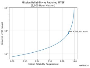
As required mission reliability approaches 100%, required MTBF increases sharply. Mission-level certainty carries architectural cost.
Audit → Design → Validate Alignment
Audit
- Define allowable DPM or mission reliability based on RoI
- Quantify financial exposure
- Establish acceptable confidence level
Design
- Architect screening, derating, redundancy, and controls to achieve the defined target
- Ensure feasibility within cost constraints
Validate
- Execute statistically defensible plan
- Demonstrate alignment between engineering evidence and business assumption
If those three are not mathematically aligned, margin becomes hope.
The Strategic Discipline Behind Certainty
Defect targets are not engineering preferences.
Reliability targets are not test outputs.
They are financial constraints defined at product conception.
Design must make them achievable.
Validation must prove them statistically.
Because certainty is not free.
But uncertainty is far more expensive.
Statistical validation does not create quality.
It proves whether your business assumptions were realistic.
ORTENGA defines products with the economic, reliability, and performance constraints required for engineering teams to design and implement scalable production systems — not prototypes.
System First, Silicon Second
How Apple Expanded Its Control of the iPhone Architecture
Silicon Real Estate Expansion Inside the iPhone
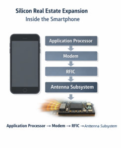
Figure — Silicon Real Estate Expansion:
Apple progressively internalizing the wireless stack inside the iPhone — from application processor to modem, RFIC, and antenna subsystem.
When Steve Jobs introduced the iPhone in 2007 at Apple Inc., he did not introduce a chip.
He introduced a system.
A phone.
An iPod.
An internet communicator.
The breakthrough was not silicon.
It was integration.
From the beginning, Apple controlled the architecture of the experience:
- Hardware design
- Operating system (iOS)
- User interface paradigm
- Power management philosophy
- Ecosystem integration
The system vision came first.
Silicon followed.
Phase I — Application Processor: Enabling the System
To realize that system vision, Apple began designing its own application processors — the A-series.
This was not semiconductor ambition for its own sake.
It was system optimization.
Owning the application processor allowed Apple to control:
- Performance per watt
- Battery life
- Thermal envelope
- Tight hardware–software coupling
Compute was pulled inward to protect the integrity of the iPhone experience.
The processor became the first layer of Apple’s silicon real estate inside the device.
Phase II — Modem: Controlling Communication
Wireless connectivity, however, remained externally supplied.
But communication is not a peripheral function in a smartphone.
It is existential.
Around 2013, Apple began building internal modem capability.
In 2019, Apple acquired the smartphone modem business of Intel Corporation.
This was not simply an expansion of engineering headcount.
It was institutional capability acquisition:
- PHY-layer engineering expertise
- 3GPP standards experience
- Carrier certification knowledge
- RF/baseband integration capability
The modem is the heart of the radio stack.
Owning it reduces external dependency and enables deeper optimization across the communication pipeline.
The architectural boundary moved outward — from compute to communication.
Phase III — RFIC: Bridging Digital and RF Physics
In recent years, Apple has expanded further into RF transceiver and RFIC development.
The RFIC bridges digital baseband processing and analog radio frequency signals.
This layer governs:
- Frequency synthesis
- Upconversion and downconversion
- Gain control
- Noise figure
- Linearity
- Power efficiency
At this stage, Apple was no longer just designing processors.
It was integrating the radio subsystem.
The architectural boundary moved again — from signal processing to electromagnetic signal transfer.
Phase IV — Advanced Antenna Subsystem
The next frontier is now increasingly visible: the antenna subsystem.
As wireless systems moved into mmWave spectrum and eventually toward 6G, antenna design is no longer modular.
It becomes a tightly integrated subsystem influenced by multiple constraints:
- Aperture limitations
- Mechanical packaging
- Thermal density
- Beam-steering control
- RF front-end interaction
At these frequencies, the antenna cannot simply be attached to the radio.
It must be co-designed with:
- Modem scheduling
- RFIC gain architecture
- Thermal distribution
- Mechanical structure
Performance is no longer determined solely by silicon.
It is determined by how effectively energy is radiated into free space.
And free space obeys physics.
Architecture Boundary Migration
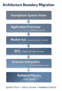
Apple’s architectural expansion can be understood as a steady migration of the control boundary outward:
iPhone System Vision
↓
Application Processor — Compute Control
↓
Modem SoC — Communication Control
↓
RFIC — Signal Transfer Control
↓
Antenna Subsystem — Radiated Performance
↓
Free Space — Physics
Each step represents a deeper level of system ownership.
Apple did not start with silicon ambition.
Apple started with system intent.
Silicon has been progressively internalized to preserve and optimize that system.
Now the boundary approaches electromagnetic space itself.
Strategic Implication
Apple’s progression illustrates disciplined architectural sequencing:
- Define the system.
- Internalize critical enabling technologies.
- Reduce external dependency.
- Optimize across layers.
- Expand control where margin and performance are strategic.
The antenna subsystem is not a cosmetic addition to this strategy.
It is the next control layer.
Because as wireless systems move toward higher frequencies:
- Aperture determines usable energy
- Thermal density limits radiated power
- Packaging influences radiation efficiency
- Beamforming stabilizes communication links
- System-level co-design determines real performance
The bottleneck moves outward.
From transistor scaling
to signal processing
to RF efficiency
to radiated physics.
The philosophy that guided the iPhone from the beginning remains visible.
Start with the experience.
Design the system.
Then build the technology necessary to realize it.
Apple’s silicon expansion is not opportunistic.
It is architectural.
From application processor
to modem
to RFIC
to antenna subsystem
The company is not simply designing more chips.
It is securing control of the system.
And as wireless technology advances toward 6G, competitive advantage will increasingly depend on mastery of radiated performance — where silicon, RF, antenna, thermal engineering, and mechanical design converge.
At ORTENGA, we work with companies at the system-definition stage to ensure that architectural intent, engineering decomposition, and validation strategy remain aligned from concept through production.
Because in advanced wireless platforms, competitive advantage is rarely created by a single chip — it emerges from disciplined system architecture across silicon, RF, antenna, and real-world performance.
Authenticate Before You Communicate
What Radio and Radar Teach Us About Structure, Trust, and Signal Integrity
With the advancement of technology and the volume of messages we receive daily, an important question arises:
What defines an appropriate message format?
Whether in business, engineering, or personal communication, effective messaging follows a disciplined structure — much like advanced radio and radar systems.
Structure Determines Whether a Message Is Received
Every day, executives, engineers, and investors receive dozens — sometimes hundreds — of messages.
Most are ignored.
Not because the information is irrelevant, but because the structure fails before the content is even considered.
In engineered communication systems, this failure would be unacceptable.
A radio does not begin transmitting payload data immediately.
A radar system does not process every reflected signal as meaningful information.
Before information is exchanged, communication systems establish structure:
- Identity
- Authentication
- Synchronization
- Environmental adaptation
Only after these steps does the payload follow.
The same principle governs effective human communication — and disciplined product development.
If identity is unclear, trust cannot be established.
If authentication is missing, engagement stops.
If synchronization fails, meaning is distorted.
Structure determines whether the receiver recognizes signal — or discards noise.
The First Step: Introduction
Any legitimate message begins with clear identification of the sender.
Examples include:
- “Hello, my name is …”
- “Blue Bank Financial …”
- “Orange Motors Service Department …”
Before the receiver evaluates the content, the sender must establish identity.
Without identity, the receiver cannot determine whether the message is relevant or trustworthy.
The Second Step: Authentication
Identification alone is insufficient.
A credible message also requires authentication.
Authentication becomes more specific, and the level of verification is typically determined or agreed upon between the sender and the receiver.
Once authentication is established, the receiver decides whether to:
- Continue receiving the message
- Or terminate the communication
This process is fundamental not only in human communication but also in engineered communication systems.
Radio Communication Follows the Same Discipline
In radio communication systems, information is transmitted in structured units often referred to as frames.
Each frame typically begins with a preamble, which performs several critical tasks before payload data is transmitted.
The preamble allows the receiver to:
- Detect the presence of a signal
- Synchronize timing and frequency
- Prepare the receiver to decode the incoming information
Systems may also transmit pilot signals for synchronization so the receiver can align itself with the incoming waveform.
Additionally, training signals may be transmitted so the receiver can construct an equalizer that compensates for distortion introduced by the radio channel.
This process allows the receiver to adapt to the environment before interpreting the message.
Handshake Before Information
Many communication protocols include a handshake process between sender and receiver.
This handshake is similar to agreeing on the language and pace of conversation before beginning a dialogue.
The sender transmits candidate signals or formats.
The receiver indicates which signals are received reliably.
Based on this feedback, the sender selects the appropriate waveform and continues communication using that format.
Waveforms are designed for specific:
- Channel conditions
- Frequency bands
- Environmental constraints
Only after this structured preparation does the sender transmit the actual information payload.
Radar Systems Also Validate Signals
Radar systems follow a similar validation discipline.
When a radar transmits a waveform, the system expects a corresponding signature when that signal reflects from a target.
However, the environment contains noise, clutter, and interference.
Before interpreting a received signal as a legitimate target echo, radar signal processing commonly applies correlation or matched-filter techniques to verify that the echo corresponds to the transmitted waveform.
Only signals matching the expected structure are processed further.
Radar waveform design itself is also influenced by:
- Target characteristics
- Frequency band
- Environmental conditions
- Operational objectives
Again, the principle remains consistent:
Validation precedes interpretation.
A Universal Pattern
Across human messaging, radio communication, and radar systems, the structure is remarkably consistent.
Communication does not begin with information.
It begins with validation of the channel and credibility of the source.
The sequence is disciplined:
- Identify the sender
- Authenticate the source
- Synchronize the interaction
- Adapt to the environment
- Deliver the payload
When these steps are skipped, the receiver cannot distinguish signal from noise.
Signal Integrity Framework
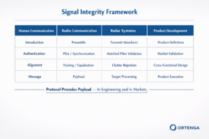
Protocol Precedes Payload — In Engineering and in Markets
Executive Insight
Advanced systems do not trust by default.
A radio receiver does not decode random energy.
A radar processor does not interpret every reflection as a target.
Signals are validated first.
Only signals that pass structural checks — identity, synchronization, and waveform conformity — are treated as meaningful information.
Everything else is rejected as noise.
The same law applies to business communication.
If a message lacks:
- Clear identification
- Credible authentication
- Alignment with the receiver’s context
- Structural discipline
It is filtered out before the content is ever evaluated.
ORTENGA Insight
Engineering rigor begins before design implementation.
Just as communication systems enforce structure before payload transmission, successful products require disciplined definition before execution.
Authentication in communication parallels validation of market need.
Synchronization in radio mirrors cross-functional alignment across hardware, firmware, and software teams.
Waveform selection parallels architectural trade-offs under real-world constraints.
Without these steps, performance claims are meaningless.
With them, signal integrity becomes competitive advantage.
In radio, protocol precedes payload.
In radar, validation precedes interpretation.
In business, structure precedes trust.
Authenticate before you communicate.
Partner with ORTENGA to define, design, and validate products with the same discipline that governs advanced communication and radar systems.
Because markets, like receivers, reject noise.
Only authenticated signal earns attention, capital, and adoption.
The Smartphone as a Sensor Platform
How Mobile Devices Are Becoming Distributed Sensing Infrastructure
For decades, mobile phones were designed primarily as communication devices. Successive generations of wireless technology focused on improving data rate, spectral efficiency, and network capacity.
However, modern mobile devices are evolving into something far more powerful.
Today’s handheld platforms integrate a growing set of embedded sensors capable of observing and measuring the surrounding physical world. Location, motion, sound, environmental conditions, and aspects of human health can now be captured directly by devices carried by billions of people.
As a result, smartphones are quietly becoming one of the largest distributed sensing platforms ever deployed.
Sensor Expansion in Modern Mobile Devices
In addition to communication capability, modern mobile devices integrate sensors that enable applications well beyond traditional voice and data services.
These sensors support capabilities such as:
- Location awareness
- Environmental monitoring
- Acoustic sensing
- Health measurements
- Hazard detection
The following chart illustrates the estimated presence of sensor categories in handheld mobile devices.
Figure 1 — Sensor Categories in Mobile Devices
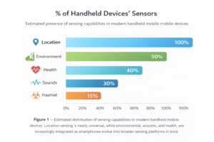
Figure 1 – Estimated distribution of sensing capabilities in handheld mobile devices. Location sensing is nearly universal, while environmental, acoustic, and health sensors are increasingly integrated as mobile platforms evolve into broader sensing systems.
The Mobile Device as a Sensing Platform
Modern smartphones now contain a sensor ecosystem enabled by advances in MEMS technology, semiconductor integration, and low-power signal processing.
These sensors allow devices to measure both user context and environmental conditions, transforming mobile devices into continuous sensing nodes.
Figure 2 — Mobile Device Sensing Architecture
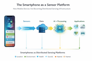
Figure 2 – Conceptual architecture of a mobile device acting as a sensing platform. Embedded sensors collect data from the physical world, which is processed and interpreted through computing and AI systems to enable applications.
From Devices to Distributed Sensing Infrastructure
The implications of sensor expansion extend far beyond the device itself.
Billions of mobile devices are already distributed across cities, homes, transportation systems, and industrial environments. When equipped with diverse sensing capabilities, these devices collectively form a large-scale sensing network capable of observing the physical world in real time.
Each smartphone effectively becomes a sensing node within a distributed information system.
Figure 3 — Distributed Mobile Sensing Network
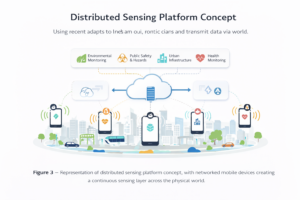
Figure 3 – Conceptual representation of a distributed sensing network where mobile devices act as connected sensing nodes that continuously collect and transmit environmental and contextual data.
System-Level Implications
The evolution of mobile devices is no longer defined solely by faster connectivity. The next phase of mobile innovation will be driven by platforms capable of sensing, interpreting, and responding to the physical world.
As sensing capabilities expand, mobile devices may become the largest distributed environmental monitoring network ever deployed.
Figure 4 — Global Sensing Infrastructure Stack
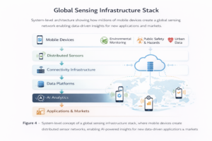
Figure 4 – System-level architecture illustrating how billions of mobile devices can collectively form a global sensing infrastructure. Data flows from distributed sensors through connectivity infrastructure into data platforms and AI analytics to enable new applications and markets.
Strategic Insight
The mobile industry is entering a new phase in which devices are not only communication endpoints but active sensing platforms within digital ecosystems.
This shift enables new capabilities including:
- Environmental monitoring
- Public safety and hazard detection
- Urban infrastructure analytics
- Health and wellness insights
- Context-aware computing
The companies that successfully integrate sensing, connectivity, and intelligent software architectures will define the next generation of mobile platforms.
ORTENGA Perspective
Technology transitions of this scale require system-level thinking across hardware, sensing, connectivity, and software architecture.
Breakthrough products rarely emerge from isolated improvements in individual technologies. Instead, they emerge from architectures that integrate sensing, communication, and intelligent software into coherent systems.
ORTENGA helps technology companies define and architect system platforms that transform emerging technologies into scalable and economically viable products.
From Small Cells to Cell-Free Networks
Why Wireless Architecture Is Becoming a Distributed Mosaic of Radios
For decades, wireless networks have been designed around a simple assumption: a small number of powerful towers radiate signals across large geographic areas.
This architecture enabled the rapid global expansion of cellular communication, connecting billions of people and transforming how societies share information, communicate, and interact.
Today a photo taken anywhere in the world can be shared instantly with friends and family across continents. Videos of personal milestones—birthdays, weddings, and important life events—can be transmitted globally within seconds.
But the forces shaping the next generation of wireless systems are fundamentally different.
Rising data demand, higher operating frequencies, and new applications such as AI-enabled services and extended reality are pushing wireless infrastructure toward a new model. Rather than relying on a few high-power towers, future networks will increasingly consist of large numbers of low-power radios distributed throughout the environment.
In this emerging architecture, connectivity will be delivered through a dense mosaic of radios embedded in cities, buildings, vehicles, and public infrastructure.
The Macro Cell Era
Traditional wireless networks were built around large macro cells.
A relatively small number of high-power base stations, typically mounted on towers or tall structures, provided wide-area coverage. These base stations often used three-sector antennas to divide coverage into large geographic regions.
This architecture prioritized broad geographic coverage with minimal infrastructure, which was appropriate for the early generations of cellular communication.
However, as wireless demand increased, the limitations of this approach became more apparent.
The Shift Toward Small Cells
As wireless systems move toward higher frequencies and higher data capacity, the propagation characteristics of radio signals change. Signals experience greater attenuation when passing through buildings, walls, and other obstacles.
At the same time, the demand for higher data rates continues to grow rapidly.
To address these challenges, network architectures are evolving toward dense deployments of small cells placed closer to users.
Unlike traditional macro towers, small cells operate with:
- lower transmit power
- shorter wavelengths (higher frequencies)
- directional or beam-steered antennas
- smaller coverage areas
Rather than relying on a few large towers, future wireless networks will increasingly consist of many low-power access points embedded throughout the environment.
This creates what can be described as a mosaic of small cells woven into the environment.
Figure 1 — Dense Mosaic of Small Cells

The figure illustrates how dense small-cell deployments create overlapping coverage areas distributed throughout urban environments.
The Next Evolution: Cell-Free Architecture
Even the concept of “cells” may eventually disappear.
Future wireless systems, particularly those envisioned for 6G, are exploring cell-free architectures. In this approach, a large number of distributed access points cooperate to serve users simultaneously rather than dividing coverage into separate cells.
Instead of connecting to a single base station, a user device may be served by multiple coordinated radios distributed across the network.
This architecture can significantly improve:
- network capacity
- service uniformity
- reliability
- spectral efficiency
The network becomes user-centric rather than cell-centric, effectively eliminating the traditional boundaries between cells.
Much of the pioneering research in this area has been led by Professor Emil Björnson, whose work on Cell-Free Massive MIMO helped establish the theoretical foundations of this emerging architecture.
A Distributed Wireless Future
The evolution of wireless infrastructure can be viewed as a progression:
Macro Cell Networks
↓
Dense Small Cell Deployments
↓
Cell-Free Distributed Radio Systems
Figure 2 — Evolution of Wireless Architecture
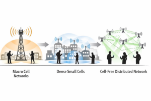 The diagram illustrates how wireless infrastructure is evolving from tower-centric networks to distributed radio systems.
Each stage moves wireless infrastructure closer to users while increasing coordination between radios.
In the long term, wireless connectivity may resemble a distributed fabric of radios embedded throughout cities, buildings, vehicles, and public spaces.
ORTENGA Perspective
Major advances in wireless technology rarely come from incremental improvements in radio components alone. They are often driven by architectural shifts in how networks are designed and deployed.
The transition from macro cellular networks to dense small-cell deployments—and ultimately toward cell-free distributed radio systems—represents one of the most significant architectural evolutions in the history of wireless communication.
As wireless infrastructure becomes more distributed, the complexity of designing and integrating these systems increases significantly. Successful deployment will require coordinated innovation across multiple engineering disciplines, including antennas, semiconductor technology, signal processing algorithms, hardware platforms, and software-defined networking.
Organizations that understand this architectural shift early will be better positioned to design scalable wireless platforms for the next generation of connectivity.
ORTENGA works with clients and stakeholders to identify system objectives, define technical architectures, and translate emerging technologies into practical engineering solutions.
With experience spanning autonomous automotive, SATCOM, radar, smart city infrastructure, Wi-Fi, and terrestrial mobile communications, ORTENGA brings multidisciplinary expertise across antenna, ASIC, algorithm, hardware, firmware, and software engineering.
Partner with ORTENGA in your next product concept, design, and development to transform innovative ideas into scalable wireless systems.
The wireless network of the future will not be defined by towers — it will be defined by a distributed fabric of coordinated radios surrounding the user.
Validation Is Not Testing
How Design of Experiments (DOE) Focuses Engineering on What Actually Matters
In fast-moving technology markets, validating a product design in months instead of a year can determine whether a company captures a high-margin opportunity or misses the market entirely.
Time-to-market (TTM) is often the difference between market leadership and irrelevance.
Yet many product development organizations still approach validation as a long checklist of tests performed after design is completed. As systems become increasingly complex—integrating RF subsystems, firmware stacks, sensors, power management, and AI algorithms—fully validating every feature can take months or even more than a year.
For many companies, this delay alone can erase the economic opportunity.
Figure 1 — ORTENGA Engineering Risk & RoI Blueprint
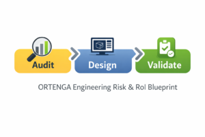
This framework aligns product intent, engineering architecture, and validation strategy so that risks are identified early and verified systematically throughout development.
The Limits of Traditional Post-Design Validation
Traditional validation strategies often rely on an implicit black-box assumption.
Validation teams treat every feature and performance metric as having equal probability of failure. As a result, the testing plan distributes effort evenly across all system functions.
In reality, this assumption rarely holds.
Certain parts of a design inherently carry greater risk, such as:
- RF front-end interactions
- Power management dynamics
- Hardware–firmware interfaces
- Environmental edge cases
When all features are treated equally in the validation plan, engineering resources become diluted across both low-risk and high-risk areas.
The consequences are predictable:
- Longer validation cycles
- Misallocated engineering resources
- Delayed product launches
- Reduced product margins
Figure 2 — Traditional Validation vs DOE-Driven Validation
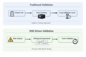 The Startup Pitfall
A typical pitfall in startup product development is planning validation only after design and development are completed.
Effective product audits instead align design and validation from the beginning, ensuring that engineering decisions are made with validation in mind.
This disciplined approach reduces technical risk, lowers development costs, and reflects the ORTENGA Engineering Risk & RoI Blueprint philosophy.
Design of Experiments (DOE)
Design of Experiments (DOE) saves time and cost by focusing validation on the variables most likely to affect system performance rather than performing blanket testing without design insight. The effectiveness of DOE, however, depends on system-level engineering insight to determine which variables and interactions must be explored.
Rather than testing every parameter independently, DOE enables engineers to evaluate multiple variables simultaneously using structured experimental matrices.
This approach allows engineering teams to:
- Identify dominant contributors to system performance
- Detect interactions between design parameters
- Reduce the number of experiments required
- Accelerate root-cause discovery
DOE transforms validation from blanket testing into focused experimentation.
Design of Experiments (DOE) saves time and cost by focusing validation on the variables most likely to affect system performance rather than performing blanket testing without design insight. The effectiveness of DOE, however, depends on system-level engineering insight to determine which variables and interactions must be explored.
Figure 3 — Orthogonal Experiment Concept
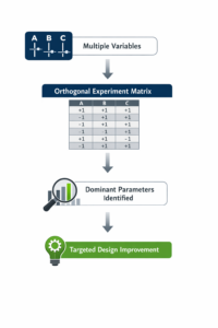
This structured experimentation approach allows engineers to uncover system sensitivities with far fewer tests than traditional validation methods.
The Manufacturing Problem That Changed Engineering
The principles behind DOE emerged from a manufacturing challenge in the 1950s, when Japanese automobile manufacturers struggled with low production yield.
Cars coming off the production line did not consistently meet performance or reliability expectations. Engineers recognized that many manufacturing parameters—such as materials, process temperatures, mechanical tolerances, and assembly sequences—were influencing product quality.
However, there were too many interacting variables to isolate the root causes efficiently.
Testing one variable at a time proved slow and expensive, often taking months or years to identify the underlying problem.
Japanese manufacturers invited W. Edwards Deming to introduce statistical quality methods into manufacturing.
Around the same time, engineer Genichi Taguchi developed experimental techniques based on orthogonal arrays, allowing engineers to extract meaningful insight from complex systems using a manageable number of experiments.
These techniques became widely known as Design of Experiments (DOE).
Validation Speed Determines Time-to-Market
Industries with aggressive product cycles illustrate the importance of disciplined validation strategies.
Consider the smartphone ecosystem.
Major handset manufacturers typically release two flagship devices per year, often around June and December. To support a June device launch, the underlying SoC, RFIC, PMIC, and ASIC platforms must reach production readiness by the previous December.
Vendors across the ecosystem often begin development at roughly the same time.
Yet only some consistently meet the schedule.
The difference is rarely engineering talent alone.
More often, it is validation methodology.
Organizations that rely on blanket testing frequently run out of time and the resulting validation cycle becomes unnecessarily expensive. In contrast, organizations that structure validation around DOE and risk-weighted experimentation identify problems earlier and reach production readiness faster.
Conversely, organizations that reduce testing without engineering insight—simply to save cost or accelerate time-to-market—risk test escapes and field reliability issues.
Engineering Principle
Validation is a balancing act that requires due diligence and a thoughtful engineering process to be both smart and effective. Validation planning must begin with design—not after it.
ORTENGA Perspective
Validation should not be treated as a checklist performed after design completion.
It is a strategic engineering discipline that determines whether a product reaches its market window.
Design of Experiments provides the statistical framework to accelerate discovery, but effective DOE depends on system-level understanding to determine which variables truly matter.
Organizations that integrate audit, design, and validation cohesively reduce development risk, accelerate time-to-market, and build products that scale to high-volume production.
Partner with ORTENGA to structure product development programs that align engineering decisions with validation strategy from the beginning—delivering production-ready systems instead of delayed prototypes.
When Product Mistakes Appear as Engineering Problems
How Misaligned Engineering Teams Quietly Delay Products and Increase Development Cost
Many engineering problems discovered during product development are not engineering failures at all.
They are the visible consequences of earlier product-level decisions that were never properly examined.
Imagine a football team where the quarterback is asked to play receiver, the linebacker is assigned to play quarterback, and the receiver is placed at linebacker.
Each player may be talented—even excellent—but they are operating outside their depth because the team has been arranged incorrectly.
The problem is not the players. The problem is the team structure.
The same situation frequently occurs in engineering organizations. Engineers are hired and assigned based on superficial criteria—such as familiarity with specific software tools—rather than deep domain expertise. Stakeholders without sufficient technical background then assemble teams where individuals are placed into roles that do not match their experience.
The result is predictable: projects struggle not because engineers lack capability, but because the engineering team was structured incorrectly from the beginning.
The Product Mistake → Engineering Problem Loop
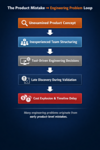
Figure 1 — The Product Mistake → Engineering Problem Loop
Many engineering problems originate from earlier product-level decisions that were never properly examined. When the product concept is not audited early, organizations often compensate with tool-driven engineering decisions and inexperienced team structuring. The consequences usually appear later during validation when the cost of correction becomes significantly higher.
The Illusion Created by Modern Engineering Tools
Modern engineering tools have become extremely powerful. RF instruments, electromagnetic simulators, and CAD platforms automate tasks that once required significant expertise.
This digital transformation has created an unintended side effect.
Because these tools are easier to operate, organizations sometimes mistake tool familiarity for engineering expertise.
A candidate who can operate simulation software or CAD tools may appear technically qualified, even though deeper domain understanding—such as antenna physics, RF tradeoffs, or system-level constraints—is missing.
This is not a failure of digital transformation itself. It is a mis-implementation of it, where powerful tools substitute for engineering judgment instead of amplifying it.
When Cost Becomes the Wrong Decision Driver
The issue is not driven by cost alone.
In many startups, inexperienced stakeholders are responsible for assembling engineering teams without the technical context required to evaluate the roles properly.
Cost then becomes the visible justification behind many hiring decisions. In practice, however, cost often becomes the convenient rationale that allows organizations to avoid confronting deeper uncertainties in the product concept.
Instead of addressing technical risks early, decisions are deferred deeper into the development cycle where they become far more expensive to correct.
A Typical Example: Antenna Design
Consider a common scenario in product development.
A startup hires a novice engineer familiar with CAD tools to design the antenna for a new product instead of hiring an experienced antenna engineer. In this case, proficiency with the CAD tool becomes the perceived technical threshold for the role.
The assumption is that the engineer will learn on the job.
During the first year, the new hire gradually learns how to communicate technically with colleagues and begins assembling design requirements. However, without deeper domain knowledge, the engineer does not fully understand the justification behind those requirements and therefore cannot meaningfully guide or challenge them.
Several months later, the antenna design phase begins.
Soon the design encounters difficulties in meeting the defined requirements. Stakeholders then face a series of technical decisions. After months of investigation, the team often chooses a variation of the original design that appears to represent a reasonable tradeoff among parameters.
Yet the true impact of those tradeoffs on the final product remains unclear.
The decision is deferred to the validation phase.
When validation finally begins, some use-case issues surface. At that stage, redesign would cost roughly ten times more and introduce delays that stakeholders find unacceptable.
As a result, a quasi-product is pushed to early adopters.
Only after customers begin using the product do the majority of the product shortcomings become evident.
The Same Pattern Appears in RF Measurement
A similar pattern appears in RF measurement environments.
Startups often hire inexperienced RF engineers because modern RF equipment appears straightforward to operate. Vendors and application engineers help configure the instruments, and the organization assumes measurement capability has been established.
Initial measurements produce data, but the results are often not repeatable.
Eventually the engineer learns that measurement setups—cables, connectors, calibration procedures, grounding, and environmental stability—are critical to producing consistent results.
The first lesson is learned.
The next challenge appears when multiple RF parameters are measured simultaneously. Individual measurements may appear correct, yet the parameters contradict each other when analyzed together.
Understanding the relationships among RF parameters requires deeper domain experience.
Without experienced guidance, this learning process can take years.
By the time inconsistencies appear across multiple DUTs, stakeholders face difficult questions: Is the problem in the design, the measurement setup, manufacturing variation, or unrealistic specifications?
The project ultimately takes longer, costs more, and still fails to produce trustworthy validation results.
The ORTENGA Engineering Risk & RoI Blueprint
Figure 2 — ORTENGA Engineering Risk & RoI Blueprint
At ORTENGA, we follow a structured framework that aligns product definition, engineering design, and validation with the intended market use cases.
The process consists of three phases.
Audit
Evaluate the product concept and its intended use cases to ensure the product targets a viable market and solves a meaningful problem.
Design
Decompose the product concept into engineering requirements with clear technical justifications. These justifications enable informed design tradeoffs and guide system architecture.
Validate
Implement the design and validate the system against the use cases defined during the Audit phase.
This disciplined structure ensures that engineering decisions remain aligned with product intent while minimizing costly late-stage redesigns.
Final Insight
Many engineering problems discovered during development are not engineering failures at all.
They are the visible consequences of earlier product-level decisions that were never properly examined.
The situation resembles a football team where talented players are assigned to the wrong positions. The players themselves may be capable—even excellent—but the system cannot perform as intended because the team structure was incorrect from the beginning.
In technology development, the earlier a product mistake is discovered, the cheaper it is to correct.
The later it appears, the more it disguises itself as an engineering problem.
Risk as a Competitive Advantage
From Technology Choices to Silicon-to-System Execution
Why Balancing Technology Risk and Reward During Product Definition Determines Startup Success and Optimizes RoI
High-tech startups face significant challenges on the path to market success. Industry observations suggest that between 60% and 90% of startups fail to gain meaningful market traction.
Yet even unsuccessful startups frequently generate valuable intellectual property (IP) during their development lifecycle.
Many deep-tech startups can be broadly categorized by the primary technology they develop:
- Algorithm / Software
- RF / Antenna Hardware
- ASIC (Application-Specific Integrated Circuit)
Each of these domains carries different levels of development risk, capital exposure, and return-on-investment (RoI) uncertainty. Understanding these differences during product definition is critical for startup survival.
Technology Risk and Reward
Algorithm, antenna, and ASIC development each carry different risk–reward profiles.
Algorithm innovation typically allows rapid iteration and lower development cost, while antenna systems introduce hardware integration complexity, and ASIC development requires long design cycles and expensive fabrication.
However, as technologies combine, the risk profile increases significantly, while the potential reward also grows.
Startups that integrate multiple technology domains may achieve higher performance and stronger differentiation, but they must manage the resulting system-level engineering risks.
Figure 1 — Technology Risk vs Reward Framework

The figure illustrates how technology choices influence both development risk and potential market reward.
Algorithm development typically carries lower risk but moderate differentiation. Antenna systems introduce greater engineering complexity, while custom ASIC solutions require substantial investment and long development cycles.
When technologies stack—such as antenna + algorithm or ASIC + algorithm—both the technical risk and the potential reward increase.
Algorithm Startups — Lower Development Risk
Algorithm-focused startups typically face the lowest development risk among the three technology categories.
Algorithms can often be designed and validated using software simulation environments such as MATLAB, Python, or C/C++ frameworks. Development cycles can range from weeks to a few months, allowing rapid iteration and relatively low capital requirements.
While algorithm innovation can create significant value, the lower barrier to entry may also result in moderate differentiation unless tightly integrated with system capabilities.
Antenna Startups — Moderate Risk
Antenna and RF hardware startups typically occupy the middle ground of technical risk.
Antenna development requires electromagnetic modeling, prototype fabrication, RF measurements, and system integration. Although iteration cycles are shorter than silicon fabrication cycles, physical prototypes are still required, introducing hardware costs and schedule risks.
However, successful antenna innovation can deliver strong system-level differentiation in areas such as wireless communications, radar, sensing, and satellite systems.
ASIC Startups — Higher Risk, Higher Reward
ASIC development generally carries the highest development risk.
Designing custom silicon involves long development cycles including architecture definition, RTL design, verification, physical implementation, fabrication, and silicon validation. Fabrication costs alone may reach millions of dollars per iteration, and design errors often require additional silicon spins.
The combination of long timelines, high cost, and limited iteration opportunities makes ASIC startups particularly exposed to capital and schedule risk.
However, when successful, custom silicon can create strong barriers to entry and significant competitive advantage.
When Technologies Combine, Risk Multiplies
Many advanced startups build products that combine multiple technology domains. Examples include:
- AI accelerator ASICs supporting proprietary algorithms
- Phased-array antennas controlled by adaptive beamforming algorithms
- RF sensing systems combining antenna hardware with advanced signal processing
These combinations can deliver superior system performance, but they also introduce compounded development risk.
ASIC + Algorithm
Developing both a new ASIC architecture and a proprietary algorithm requires both technologies to mature successfully. Algorithms may evolve rapidly, while ASIC iterations require long silicon fabrication cycles, creating a mismatch in development timelines.
Antenna + Algorithm
In antenna-algorithm systems, algorithm performance depends on the real electromagnetic characteristics of the antenna. Variations between simulation and hardware measurements can significantly impact system performance.
As technologies stack, development becomes system-level engineering rather than component-level engineering.
Risk and Reward in Deep-Tech Innovation
Higher technical risk can also create greater strategic reward.
Startups that successfully integrate multiple technology domains may achieve:
Technology Differentiation
Integrated systems often deliver capabilities that competitors cannot easily replicate.
Higher Barriers to Entry
Competitors must replicate not just one component but an entire system architecture.
Stronger Intellectual Property
Multi-domain innovation frequently generates broader and more defensible patent portfolios.
Market Leadership
Successful integration can define entirely new product categories.
The goal is therefore not to eliminate risk, but to ensure that potential reward justifies the risk being taken.
Why Many Startups Fail
The challenge is rarely the underlying technology itself.
More often, startups fail because the balance between risk and reward is not properly incorporated into the product concept and definition stage.
Many teams pursue technically ambitious ideas without aligning:
- technology complexity
- development timelines
- capital requirements
- system integration challenges
- market timing
When these factors are misaligned, development risk can exceed available resources or realistic market opportunity.
This imbalance is a major contributor to the widely observed statistic that 60–90% of startups fail to gain market traction.
Managing Risk Across the Silicon-to-System Stack
In regulated industries such as automotive, aerospace, radar, and SATCOM, technical risk extends beyond engineering challenges. It becomes a business, safety, and regulatory risk.
Successful programs must manage risk across the entire technology stack:
- Silicon / ASIC architecture
- Algorithms and firmware
- RF and antenna performance
- Hardware integration and thermal design
- Software validation and interoperability
- System certification and regulatory compliance
When these risks are addressed late in development, they often lead to schedule delays, redesign cycles, certification setbacks, and capital inefficiencies.
However, when managed systematically from the beginning, risk becomes a competitive advantage.
ORTENGA Engineering Risk & RoI Blueprint
Successful deep-tech products require a disciplined engineering process that aligns technology risk, market opportunity, and system execution.
The ORTENGA methodology approaches this through a structured framework:
Audit | Design | Validations
Audit
Define market intent, use cases, and business justification.
Design
Translate system intent into architecture and engineering requirements across hardware, firmware, and software.
Validations
Implement and verify the system against the defined use cases to ensure performance, reliability, and regulatory compliance.
This Silicon-to-System approach enables early identification and mitigation of risks across the entire development chain.
Final Insight
Most startup failures are not technology failures.
They are product definition failures, where the balance between technology risk and potential reward was never properly designed into the system architecture.
Organizations that understand this balance—and manage risk across the entire Silicon-to-System stack—can transform technical uncertainty into predictable execution and market leadership.
ORTENGA Engineering Risk & RoI Blueprint
Audit | Design | Validations
Turning Technical Risk into Market Advantage.
Before You Design: A Practical Due-Diligence Process for Selecting Electrical Components
Reducing integration risk when evaluating antennas, filters, ASICs, and RF devices
Selecting electrical components—such as antennas, RF filters, ASICs, sensors, or integrated modules—requires more than reviewing marketing claims.
Once a component is integrated into a product architecture, replacing it later can introduce significant delays, redesign cost, and schedule risk. For RF and high-frequency systems in particular, component substitution can cascade through the entire design.
Because of this, component down-selection should follow a disciplined evaluation process before engineering teams commit valuable laboratory resources.
Figure 1 — Electrical Component Verification Workflow
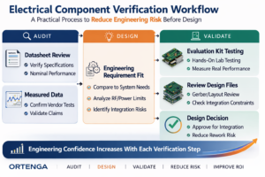
This workflow reflects a structured engineering approach aligned with the ORTENGA Engineering Risk & RoI Blueprint (Audit → Design → Validate).
Each step increases confidence that the component will perform as expected once integrated into the final system.
Why Early Verification Matters
Evaluating components consumes significant internal resources:
- Engineering design time
- RF and system test equipment
- Laboratory access
- PCB fabrication and integration cycles
Before committing these resources, it is important to determine whether the vendor has already performed the necessary technical validation for their product.
A vendor that actively supports its components will normally provide clear technical artifacts demonstrating the maturity of the device.
Minimum Artifacts a Vendor Should Provide
Before considering laboratory evaluation, request the following documentation.
- Product Datasheet
A datasheet should include at least the typical or nominal electrical performance of the component.
Depending on the device, this may include:
- Gain or efficiency (antennas)
- S-parameters (filters and RF devices)
- Noise figure or linearity
- Power consumption
- Frequency response
- Operating conditions
The datasheet provides the first indication that the vendor has characterized the device.
- Measured Performance Data
Beyond the datasheet, vendors should provide actual measured data collected during characterization.
Examples include:
- S-parameter plots
- Radiation patterns for antennas
- Power compression measurements
- Noise or sensitivity measurements
- Temperature or environmental variation data
This information helps determine whether the published specifications are supported by real measurements.
- Engineering Requirement Fit
If the measured data aligns with the published specifications and matches the requirements of your application, the next step is to evaluate how well the device fits within the system architecture.
At this stage engineers compare:
- performance requirements
- power and RF constraints
- integration considerations
- Request an Evaluation Kit
An evaluation kit allows engineering teams to independently verify:
- Electrical performance
- Interface compatibility
- Integration constraints
- System-level behavior
Evaluation kits significantly reduce risk because they allow testing before committing to a full design integration.
- Review Evaluation Board Design Files
For deeper integration planning, request the Gerber files or PCB layout files for the evaluation board.
These files provide insight into:
- Layout constraints
- Grounding strategy
- RF routing practices
- Matching networks or supporting circuitry
This information helps engineering teams understand how the device was characterized and how it should be integrated into a production design.
Figure 2 — Vendor Maturity Indicator
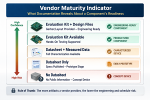
Vendor readiness can often be inferred from the technical artifacts they provide.
| Vendor Artifacts | Vendor Maturity |
| No datasheet | Concept device |
| Datasheet only | Early prototype |
| Datasheet + measured data | Characterized device |
| Evaluation kit available | Productized component |
| Evaluation kit + design files | Engineering-ready component |
If a vendor cannot provide these artifacts, the engineering risk shifts from the vendor to the customer.
Reducing Component Selection Risk
Component evaluation is a small step in the overall product lifecycle, but mistakes at this stage can propagate into costly redesigns later.
Applying structured due diligence early allows organizations to allocate engineering resources efficiently and avoid integration surprises.
ORTENGA helps companies down-select appropriate electrical components—antennas, ASICs, RF modules, and algorithmic subsystems—by translating product requirements into verifiable engineering specifications before design commitment.
The Hidden Cost of Skipping Product Decomposition
Technical Risk Begins at the Product Concept
When Product Development Starts Too Early
Many startups begin product development incrementally while performing technical decomposition gradually. They start designing the product as soon as they understand a portion of the system—usually the portion where they already have expertise or engineering resources available.
The reasoning sounds practical:
- We understand this subsystem.
- We can start building immediately.
- We will determine the remaining requirements as we learn more.
On the surface, this approach appears logical. The product eventually has to be designed, resources are limited, and starting early seems to accelerate time-to-market.
However, this approach often contains a structural weakness that becomes visible two to three years into advanced high-technology programs.
The Hidden Pitfall
When development begins before the product concept is properly decomposed, the system architecture becomes driven by what can be built first, rather than what the product ultimately requires.
Subsystems begin to evolve independently:
- Antenna systems
- ASIC architectures
- Algorithms
- Packaging
- Power management
Each engineering team may perform excellent work within its domain. Yet the product as a whole gradually drifts away from the original intent because system-level coordination was never fully established.
The consequences rarely appear early. Early prototypes often function well because they validate individual subsystems.
The real problems emerge during system integration, when the product must satisfy all constraints simultaneously.
A Simple Analogy
Skipping product concept decomposition is similar to building a house one room at a time without first creating a design blueprint.
A builder might start with a kitchen because the materials are available, then add a bedroom when space allows, and later attach a bathroom wherever plumbing appears convenient.
Each room may be built well. The carpentry could be excellent, the plumbing reliable, and the electrical wiring properly installed.
But without an architectural blueprint guiding the layout, the final result would not resemble a coherent house.
It would be a collection of disconnected rooms—more like a shack than a well-designed home.
Product development behaves in much the same way. Without decomposing the product concept into a system architecture first, engineering teams may build technically sound subsystems that ultimately fail to integrate into a successful product.
Figure 1 — Incremental Development vs Structured Product Decomposition
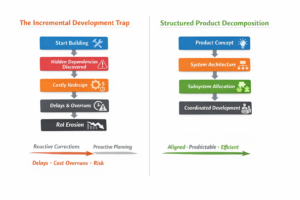
Left: Development begins before architecture is defined, leading to hidden dependencies, redesign cycles, delays, and RoI erosion.
Right: Structured product decomposition establishes system architecture first, enabling coordinated engineering and predictable outcomes.
What Gets Missed Without Product Decomposition
When development begins before the product concept is fully decomposed, several critical elements are often overlooked.
Risk–Reward Analysis
Without a full system view, organizations cannot properly evaluate the technical risk relative to the expected product value.
Complex high-technology product development involves intricate interdependencies among subsystems such as antennas, RF front ends, ASIC capability, algorithm complexity, power consumption, and packaging constraints.
The success of one subsystem often depends on the behavior of others. Evaluating risk in isolation can therefore produce misleading conclusions.
A realistic risk assessment must consider how the success or failure of one subsystem influences the feasibility of others. In complex systems, these conditional relationships can be quantified using probabilistic reasoning such as Bayes’ rule, which evaluates the likelihood of outcomes based on interdependent events.
Without decomposing the product architecture and understanding these dependencies, organizations cannot accurately quantify technical risk.
As a result, teams may unknowingly pursue product architectures whose combined technical risks make the probability of success far lower than expected.
Interdependencies Between Product Subsystems
Complex products contain tightly coupled components—such as antenna systems, ASIC architecture, signal processing algorithms, packaging, and power management.
These elements do not operate independently. Performance or constraints in one subsystem directly influence the feasible design space of others.
Without early concept decomposition, these interdependencies remain hidden. Subsystem teams may optimize their designs independently based on local objectives.
These dependencies typically surface during system integration, when all subsystems must operate together under real performance, power, thermal, and cost constraints.
Resolving these conflicts frequently requires architectural redesign, introducing delays and additional development costs.
Proper Trade-offs Between System Blocks
System design is fundamentally about trade-offs:
- power versus performance
- latency versus complexity
- cost versus capability
- thermal limits versus processing throughput
Achieving the optimal architecture requires evaluating these trade-offs across the entire system.
When subsystems evolve independently, engineering teams naturally optimize according to local objectives rather than the overall product outcome.
Consequently, limited engineering resources may be committed to misunderstood priorities, while the true system bottlenecks remain unaddressed.
Critical constraints may only become visible late in development when correcting them is significantly more expensive.
Early product concept decomposition enables teams to evaluate trade-offs at the system level, ensuring resources focus on solving the constraints that matter most.
Clear Handoff Boundaries Between Engineering Domains
Effective product development requires well-defined interfaces and responsibility boundaries between hardware, firmware, and software teams.
Without proper concept decomposition, these interfaces remain ambiguous. Teams may proceed with different assumptions about system requirements, data flows, timing constraints, or performance responsibilities.
These mismatches typically surface during system integration, requiring rework across multiple engineering domains.
Beyond technical inefficiencies, this ambiguity often creates unnecessary tension between engineering teams and management, slowing decision-making and creating development roadblocks.
The result is longer time-to-market and creeping development costs.
Time-to-Market Delays
Architectural issues discovered during system integration often require redesign of multiple subsystems.
These corrections frequently consume far more time than what was initially saved by starting development early.
Product Development Cost Creep
Late-stage design corrections are significantly more expensive than early architectural decisions. Additional prototypes, redesign cycles, and engineering hours gradually increase the development cost beyond initial projections.
Return on Investment (RoI) Erosion
As development delays accumulate and costs rise, the commercial window narrows. In extreme cases, the product may reach the market too late to capture the opportunity it was originally designed to address.
Engineering Discipline Before Engineering Speed
Skipping product concept decomposition does not eliminate complexity.
It simply delays when that complexity becomes visible, often until the most expensive stage of the program.
The fastest path to market is not starting engineering earlier.
The fastest path is clarity of architecture before execution.
ORTENGA Engineering Risk & RoI Blueprint
Successful technology organizations often follow a structured engineering framework:
Audit → Design → Validate
Audit
Clarifies business objectives and defines product use cases.
Design
Decomposes the product concept into system architecture and technical requirements.
Validate
Confirms that the implemented design satisfies the technical requirements derived during the Design phase and fulfills the use cases identified during the Audit phase.
ORTENGA can partner with organizations at any stage of new product development, engaging during the Audit, Design, or Validation phases of the program to help reduce technical risk and protect return on investment.
In advanced technology systems, successful products require more than a high-level architecture. The architecture must be systematically decomposed into well-defined system blocks, interfaces, and responsibilities so that engineering teams and stakeholders can execute the design coherently.
Successful products are not built by assembling good subsystems; they are built by decomposing a coherent architecture that those subsystems can implement.
How to Find the Right Application for Your Technology
Turning Material, Component, and System Innovation Into Product-Market Success
You’ve developed a promising technology.
It may start as:
- A new material (e.g., dielectric, substrate)
- A novel process (e.g., PolyStrata®)
- A high-performance component or subsystem
The performance is compelling.
The engineering is sound.
Yet one critical question determines success:
👉 Where should this technology actually be used?
The Right Framework
Finding the right application is not guesswork.
It is a structured process that connects:
Material → Process → Component → System → Product → Market
Figure 1 — From Innovation to Market Alignment
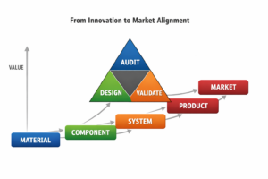
👉 This figure represents the full stack where value is either created—or lost.
It also highlights the ORTENGA methodology:
Audit → Design → Validate
applied across the stack to ensure alignment before scaling.
The Real Problem
Most teams approach this backwards.
They:
- Pick a target market first
- Try to force-fit the technology
- Then iterate when traction doesn’t come
This leads to:
- Misaligned products
- Wasted development cycles
- Delayed or lost revenue
👉 The issue is not the technology.
👉 It is the application selection.
A 5-Step Framework to Identify the Right Application
Step 1 — Identify the True Technical Advantage
Start by isolating what your technology does meaningfully better than alternatives.
Examples:
- Lower insertion loss → improved efficiency and range
- Higher dielectric control → better miniaturization
- 3D structures → waveguide-like performance in compact form
👉 This is your technical leverage point.
Step 2 — Translate Advantage Into System-Level Impact
Technology alone does not create value.
Systems create value.
Ask:
- Does this improve link budget?
- Reduce power consumption?
- Enable new architectures?
- Shrink size or weight?
👉 This is where real differentiation happens.
Step 3 — Map to Markets That Value That Impact
Different markets reward different outcomes:
- Defense / Aerospace → performance, robustness
- SATCOM → power, weight, efficiency
- Telecom → density, cost-performance
- Automotive → cost, reliability, volume
👉 Alignment is everything:
Your advantage must match what the market is willing to pay for.
Step 4 — Validate Across the Stack
Validation must extend beyond the innovation itself:
- Material → consistency and manufacturability
- Component → repeatability and performance
- System → integration and real-world behavior
- Product → cost, compliance, reliability
👉 This is Material-to-System validation.
Step 5 — Scale Only When the Stack Is Proven
Scaling amplifies everything.
If the foundation is weak:
- Costs escalate
- Yield suffers
- Market adoption fails
If the foundation is strong:
- Growth becomes predictable
- Margins improve
- Adoption accelerates
Closing Insight
Technology does not fail because it lacks performance.
It fails when:
- It is applied to the wrong product
- It is placed in the wrong market
- It is scaled at the wrong time
👉 The right application is not obvious—it is engineered.
Turn innovation into product.
Turn product into market success.
Turn investment into return.
Partner with ORTENGA to align your technology with the right product and market—driving monetization and protecting return on investment.
The Hidden Cost of Hourly Engineering Engagement
How Reactive Scope and Undefined Planning Erode Schedule, Margin, and RoI Compared to Outcome-Based Models
Executive Summary
Engineering engagement models are often treated as a procurement decision—hourly versus outcome-based—without fully understanding their impact on execution, risk, and return on investment.
In highly technical programs where RoI is critical, the engagement model directly influences how scope is defined, how schedules are managed, and how margins are preserved.
Hourly engagement introduces flexibility at the task level but often lacks upfront definition of project intent. Scope is assigned incrementally, interdependencies emerge during execution, and decisions become reactive. As a result, schedule slip, scope creep, and margin erosion are not exceptions—they are common outcomes.
In contrast, outcome-based engagement requires the program to be defined before execution begins. Deliverables are measurable, scope is locked, and schedule and budget are aligned to the intended outcome. This structure enables early identification of risks, disciplined execution, and predictable results.
The difference is not in engineering capability—it is in how the work is structured. Programs that begin without proper definition do not fail due to lack of effort. They underperform because critical decisions are deferred into the execution phase, where correction is more costly and less effective.
The engagement model determines where uncertainty lives—in planning or in execution.
CORE PRINCIPLE
Audit defines intent. Design decomposes it. Validation confirms alignment.
Audit establishes true product intent by distinguishing actual market requirements from perceived goals, and defines scope, constraints, and success criteria.
Design translates that intent into executable engineering architecture, identifying interdependencies, tradeoffs, and technical requirements.
Validation implements the design and verifies alignment with the defined scope, use cases, and performance expectations.
Skipping the Audit phase does not accelerate execution. It shifts uncertainty into development, where it manifests as scope creep, schedule instability, and margin erosion.
Introduction
In many engineering organizations, hourly engagement is viewed as a low-commitment, flexible way to access external expertise. It allows teams to start quickly, defer decisions, and adjust direction as new information emerges.
However, in highly technical programs, this perceived flexibility often comes at a cost.
Engineering systems are not independent tasks stitched together over time. They are interconnected architectures where decisions in one domain directly impact constraints in another. When these interdependencies are not defined upfront, they are discovered during execution—when the cost of change is significantly higher.
As a result, what begins as flexibility often evolves into reactive execution.
The Challenge
When advance planning is skipped—particularly during the Audit phase—the program is set up for downstream instability.
Scope is not defined—it is discovered.
Interdependencies are not planned—they are uncovered.
Constraints are not owned—they are negotiated during execution.
This leads to a predictable pattern:
- Scope expands as gaps are identified midstream
- Design iterations increase due to late discovery of dependencies
- Decision-making becomes reactive rather than structured
The impact is not limited to engineering inefficiency.
Schedule slip becomes measurable.
Budget expands without proportional value creation.
Margins compress as execution absorbs the cost of late decisions.
In high-RoI programs, time is not a neutral variable. It is a financial parameter. Any delay directly erodes return.
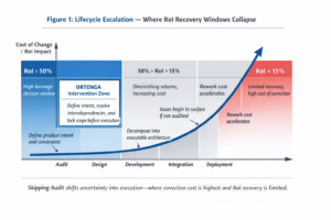
Figure 1: Lifecycle Escalation — Where RoI Recovery Windows Collapse
Figure Insight:
Early-phase decisions carry the highest leverage on RoI. Skipping the Audit phase shifts uncertainty into execution, where the cost of correction increases exponentially and recovery becomes limited.
Hourly Engagement: Flexibility with Hidden Risk
Hourly engagement operates on incremental scope definition. Tasks are assigned on a rolling basis, often without full visibility into the end objective.
This model introduces several structural challenges:
- Lack of a fixed scope leads to continuous reinterpretation of objectives
- Timeline remains fluid due to unresolved interdependencies
- Budget becomes reactive rather than predictive
- Program oversight is fragmented across stakeholders
Because the engagement is not structured around a defined outcome, engineering progresses—but not toward a fully defined or audited system.
The result is not failure in execution effort. It is misalignment in execution direction.
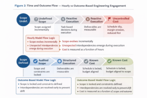
Figure 2: Time and Outcome Flow — Hourly vs Outcome-Based Engineering Engagement
Figure Insight:
Hourly engagement drives incremental scope definition and reactive execution, leading to uncontrolled cost. Outcome-based engagement aligns scope, schedule, and budget upfront, enabling predictable execution and measurable outcomes.
Outcome-Based Engagement: Structure for Predictable Execution
Outcome-based engagement requires the end objective to be clearly defined before execution begins.
Deliverables are measurable.
Scope is locked.
Schedule is aligned to execution milestones.
Budget is negotiated as a function of scope and timeline.
This structure forces critical decisions to be made early:
- What is the product intent?
- What are the system-level constraints?
- What interdependencies must be resolved before execution?
By addressing these questions upfront, the program avoids late-stage surprises and enables disciplined engineering execution.
Outcome-based engagement does not eliminate risk. It relocates risk to the phase where it is least expensive to manage.
Implications for RoI
The engagement model directly determines where uncertainty resides in the program.
- In hourly engagement, uncertainty is carried into execution
- In outcome-based engagement, uncertainty is resolved before execution
This distinction has direct financial implications:
- Late discovery of issues increases rework cost
- Schedule delays impact market timing and revenue realization
- Engineering effort is consumed correcting direction rather than advancing it
What appears as flexibility in hourly engagement often translates into uncontrolled cost and reduced RoI.
In hourly engagement, engineering effort is consumed managing uncertainty. In outcome-based engagement, engineering effort is applied toward delivering defined value.
Best Practice Framework
To align engineering execution with business objectives, leading organizations adopt a structured approach:
- Audit
Define product intent, use cases, constraints, and success criteria
Identify interdependencies across system domains
Establish a defensible and measurable scope - Design
Decompose system intent into executable engineering architecture
Define technical requirements across hardware, firmware, and software
Evaluate tradeoffs and feasibility before commitment - Validate
Implement the design in alignment with defined requirements
Verify performance against intended use cases and constraints
Ensure that the outcome matches the original product intent
This sequence ensures that engineering execution is not only technically sound, but also aligned with RoI objectives.
Executive Takeaway
Hourly engagement optimizes for short-term flexibility but often introduces long-term uncertainty in scope, schedule, and cost.
Outcome-based engagement requires upfront discipline but enables predictable execution and controlled risk.
The decision is not about contracting preference.
It is about where you choose to absorb uncertainty.
In high-stakes engineering programs, deferring definition does not preserve flexibility—it compounds cost.
Next Step
Would you like to define an executable Statement of Work aligned with your product intent, constraints, and RoI objectives?
ORTENGA works with clients to:
- Audit product concepts before engineering commitment
- Decompose system intent into executable engineering scope
- Structure engagements for predictable delivery and measurable outcomes
Schedule a 15-minute discussion:
https://calendly.com/shahram-shafie/15-minute-consultation
About ORTENGA
ORTENGA operates as a silicon-to-system engineering leadership model—integrating domain-specific expertise across antenna, ASIC, and algorithm disciplines to evaluate and realize value across applications.
We support high-complexity engineering programs through structured Audit, Design, and Validation—ensuring alignment between product intent, technical execution, and business outcomes.
Product Success Is Defined Before Engineering Begins
Why entrepreneurs and investors must align use case, feature importance, and business value upfront
Executive Summary
Most products that underperform do not suffer from poor engineering.
They suffer from incomplete definition before development begins.
Entrepreneurs often start with a strong technical vision, focusing on features and capabilities while deferring the business case. Conversely, investors and business leaders may begin with a clear monetization strategy but lack a grounded understanding of the technical use cases required to realize it.
In both scenarios, capital is deployed before a critical question is resolved:
Which features are essential for adoption—and which features actually create value?
This distinction is not intuitive. It cannot be assumed. It must be derived through structured analysis.
Some features are non-negotiable. Without them, the product is not even considered. Others enhance performance but do not influence buying decisions. Only a subset of features truly drive pricing power and return on investment.
When these are not clearly identified and aligned, products are built that function—but do not win.
At ORTENGA, this alignment is established through a structured approach: Audit, Design, and Validation—ensuring that engineering execution leads to both technical success and measurable return.
Section 1: The Hidden Starting Point of Product Failure
Most product failures are not visible at launch.
They are embedded much earlier—at the moment the product concept is defined.
A team begins with a compelling idea:
- A new capability
- A differentiated feature
- A perceived market need
Engineering progresses. The product works.
Yet later:
- Adoption is limited
- Pricing power is weak
- Margins are constrained
This is often misdiagnosed as a market issue or execution gap.
It is neither.
The product was never fully defined in terms of both use case and business value.
Consider a simple example.
A calculator performs mathematical operations. That is its use case. But whether that functionality creates value depends entirely on context—who uses it, when, and under what constraints.
Similarly:
- Some features are expected and invisible
- Some features are required for consideration
- Only a few features drive selection and margin
Identifying which is which requires structured due diligence before development begins.
Section 2: Use Case vs Business Case — Not a Comparison, but a Coupling
The distinction between use case and business case is often framed as a comparison.
That framing is misleading.
They are not separate decisions. They are a coupled system.
Use Case Defines Functional Necessity
The use case answers:
- What problem is being solved
- Under what conditions
- With what constraints
It drives:
- Technical requirements
- Feature definition
- System architecture
Business Case Defines Economic Viability
The business case answers:
- Who is willing to pay
- Under what conditions
- At what margin
It drives:
- Pricing power
- Market positioning
- Return on investment
Where They Intersect: Feature Importance
The coupling occurs at a critical point:
Feature importance is where use case meets business case.
A feature becomes:
- Must-have — absence leads to rejection
- Value-driving — enables adoption and pricing power
- Table stake — expected but not monetizable
Figure 1: Feature Importance vs Value Contribution Framework
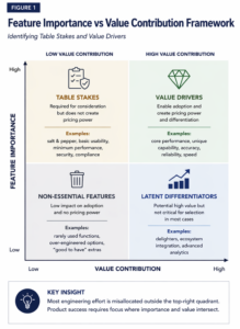
Key Insight: Most engineering effort is misallocated outside the intersection of high importance and high value contribution.
System-Level Insight
- Use case without business case → functionality without return
- Business case without use case → strategy without feasibility
Only when both are defined together can feature importance be understood.
Section 3: Table Stakes vs Value Drivers — Why Some Features Don’t Increase Price
Figure 2: Feature–Value Misalignment Over Time
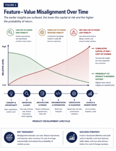
Key Insight: The later the misalignment between features and value is discovered, the higher the capital at risk and the lower the probability of success.
Not all important features create economic value.
Many features are required—but not rewarded.
Table Stakes: Mandatory but Not Monetizable
Table stakes are expected.
- Their absence → rejection
- Their presence → no pricing power
Examples:
- Salt and pepper at a restaurant
- Basic usability
- Minimum performance and reliability
They define entry—not success.
Value Drivers: Essential and Monetizable
Value drivers influence selection and enable pricing.
Examples:
- Superior performance under real constraints
- Unique capability
- Faster time to result
They convert functionality into economic return.
Why the Distinction Matters
When confused:
- Engineering focuses on the wrong problems
- Budgets are consumed without return
- Pricing power remains limited
- Differentiation is weak
Most teams:
- Overinvest in table stakes
- Underinvest in value drivers
System-Level Insight
A successful product does not maximize features.
It satisfies all table stakes and selectively excels in a small number of value drivers.
CORE PRINCIPLE
Table stakes determine whether the product is considered.
Value drivers determine whether the product is chosen.
Final Insight
A product can meet every requirement and still fail.
If it only delivers table stakes, it becomes a commodity.
And commodities do not command margin.
Call to Action
Are you confident your product concept identifies the true value drivers—before engineering begins?
If not, that risk compounds with every month of development and capital committed.
Audit your product concept before it is too late.
Schedule a 15-minute discussion:
https://calendly.com/shahram-shafie/15-minute-consultation
About ORTENGA
ORTENGA operates as a silicon-to-system engineering leadership model, integrating domain-specific expertise across antenna, ASIC, and algorithm disciplines to evaluate and realize product value across applications.
We support high-complexity engineering programs through a structured approach:
- Audit — Define product intent, use cases, and business alignment
- Design — Decompose into executable system architecture and requirements
- Validation — Ensure alignment between technical performance and business outcomes
The objective is clear:
Align product definition, engineering execution, and return on investment—before capital is fully committed.
Why Deep-Technology Customer Discovery Often Fails
The Missing Layer Between Technical Innovation and Product Direction
Many deep-technology startups assume that extensive customer discovery naturally leads to product clarity.
In practice, companies can spend months gathering feedback, interviewing stakeholders, and engaging external sales or marketing resources—yet still fail to converge on a meaningful product direction.
The common assumption is that having the inventor or technical founder involved in the discussions is sufficient to interpret customer feedback correctly.
However, invention expertise and system-level product interpretation are not the same function.
Founders and inventors are naturally close to the technology they created. This often leads to attachment to specific capabilities, broad interpretation of market interest, and unconscious bias toward validating the invention rather than challenging assumptions.
At the same time, even highly technical inventors may not fully evaluate deployment realities, system-level constraints, workflow implications, integration friction, operational economics, or how external systems absorb the technology.
As a result, customer interviews can produce activity—but not direction.
The issue is often not lack of customer feedback.
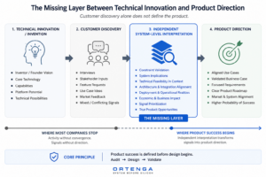
The issue is that the signals are interpreted through the same internal assumptions that defined the product in the first place.
Technical understanding does not only influence how feedback is interpreted. It fundamentally shapes:
- which questions are asked,
- which stakeholders are selected,
- what constraints are explored,
- and which signals are treated as meaningful.
Without independent system-level interpretation, customer discovery efforts often remain confined within the same conceptual boundaries that originally shaped the product.
Independent audit is required not because internal teams lack technical capability, but because system-level product interpretation requires separation from invention ownership itself.
Product success is defined before design begins.
Independent audit exists to challenge assumptions, validate constraints, and align product intent with real-world system behavior before additional capital and schedule are committed.
Customer discovery alone does not guarantee product direction.
Without independent system-level interpretation, even technically sophisticated discovery efforts can consume significant time and capital while still failing to answer the most important question:
Are we defining the right product for the right system and market?
Why Undefined Scope Leads to Endless Exploration

Many high-technology organizations begin projects by mapping the problem to its most visible attributes.
But the visible attributes are not always the governing attributes.
Those assumptions often originate from limited system-level understanding of the governing dynamics underneath the problem and incomplete domain knowledge.
Once visible-attribute assumptions are accepted as truth, they begin overriding stronger signals pointing toward the governing dynamics underneath the problem.
I have seen similar patterns in high-technology startups, where organizations continue recruiting, restructuring teams, extending discovery efforts, or searching for new expertise while operating inside an incorrectly defined problem space.
This often places organizations on the wrong path, where they may never recognize the Subject Matter Expert capable of reframing the actual problem.
A true Subject Matter Expert redefines the problem before attempting to solve it.
A true project sponsor is open to that refinement from the very beginning.
What visible-attribute assumptions are shaping your project before execution begins?
Audit your project assumptions before committing additional time, capital, and organizational momentum:
https://ortenga.net/project-discovery-request/
Your Startup Isn’t Understaffed. It’s Unscoped.
A framework for diagnosing Position Creep in early-stage startups
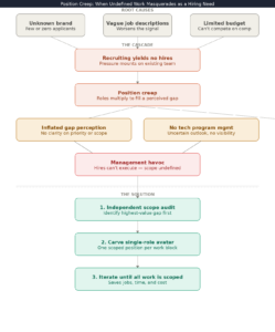
Every early-stage startup hits the same wall. Recruiting is slow, candidates are scarce, and the pressure to deliver keeps mounting. The instinct is to open more positions. But what if the problem isn’t headcount at all?
The Recruiting Trap
High-tech startups face a compounding disadvantage in hiring. They’re unknown, so the applicant pool is thin to nonexistent. Their job descriptions are vague, which makes the signal worse. And their budgets can’t compete with established players. The result: recruiting yields no hires, while the team already in place absorbs more and more pressure to deliver for the scarce customers they’ve already committed to.
What Position Creep Actually Is
When the hiring pipeline stalls, something predictable happens: positions multiply. Leadership sees unfinished work everywhere and concludes they need more people. But look closer, and most of that work could be handled by a handful of the right engineers — if anyone could agree on what needed to get done and when.
The gap appears larger than it is, not because the work is enormous, but because no one has defined it. Priorities are unclear. Timelines are undefined. The scope shifts depending on who’s in the room. This is Position Creep: undefined work masquerading as a staffing shortage.
Why It Gets Worse Before It Gets Better
The root cause is almost always the same: inadequate technical program management, combined with poor visibility into the outlook. Without someone who can translate ambiguity into executable scope, management operates in a fog. Decisions become reactive. New hires get onboarded into undefined roles and can’t move the needle — not because they’re wrong for the job, but because the job itself was never real.
This is the moment that breaks new managers. They inherit a situation where positions are open, budgets are strained, delivery is behind, and no one can explain exactly why.
The Fix Is Not More Hiring
The solution is not to fill the positions. With a limited budget and an active recruiting problem, that’s not even possible. The solution is to stop and audit the work itself — independently, rigorously, and without political deference to whoever owns what.
Start with the highest-value gap. Identify the work that matters most to the business right now, and define what it actually requires to execute. Then carve out a single role — one position avatar — that can own and accomplish that work. Once that’s done, move to the next priority. Define it. Carve the next role. Repeat until every piece of work has a defined scope and a clear owner.
Done properly, this process routinely saves what looked like five, six, or seven headcount down to two or three — with better outcomes. It also clarifies duration: how long each role is actually needed, which is often far shorter than a permanent hire would imply.
The result is not just cost savings. It’s the kind of organizational clarity that lets a small team execute like a much larger one.
The Takeaway
If your open positions keep multiplying and delivery keeps slipping, don’t add more seats to the table. Audit the work. Define the scope. Then hire — precisely, intentionally, and only for what the work actually requires.
Position Creep is a management problem wearing a recruiting costume. Treat it accordingly.
Don’t Gamble With Your Product in an Unknown Market
Most high-tech founders treat market selection like a roulette spin. 🎰

They build a great ASIC — and then hope it lands on the right market.
SatCom? Radar? Drone? Smart City? 6G? WiFi?
That’s not a strategy. That’s a gamble.
And it’s an expensive one.
Every month spent chasing the wrong market burns R&D budget, IP investment, and — most critically — time. In commercial markets, your product has roughly a 2-year design opportunity window before it becomes obsolete.
The founders who win approach this differently. From day one — product concept phase — they identify the right market. And that single decision unlocks everything:
✅ Total Addressable Market (TAM) becomes quantifiable
✅ A real market share goal becomes possible
✅ Competitor analysis becomes meaningful
✅ Product positioning becomes clear
Without market focus, you collect learning from many segments but gain insight from none.
Structure beats chance — before the clock runs out.
The AI stack, mapped. The risk and opportunity in the eyes of one investor.
Al Tarar, Chairman and Managing Partner at Quartus Capital Partners, breaks down how he navigates the AI ecosystem and where he sees the real opportunity today.
The framework starts with understanding the full stack (see diagram).
On layers 1 to 3, Al’s view is clear: these layers are profitable but the risk profile is steep. Massive capital requirements, competition concentrated among a handful of tech giants, and significant bubble risk make them extremely hard to access for growth equity investors. His approach: let the hyperscalers fund the infrastructure, and license what they build.
Layer 4 is where most AI startups operate today: productivity tools, copilots, workflow automation. But without proprietary data or deep domain expertise, these businesses commoditize quickly.
Layer 5 is where Al sees the structural edge. Vertical AI companies, particularly in healthcare, aren’t just applying AI. They’re building on datasets that no one else can replicate. Al points to Large Medical Models analyzing 700,000+ multi-dimensional data points per patient as the kind of domain-specific moat that generic models simply cannot compete with.
Layer 6, physical AI and robotics, is the frontier Al is watching closely as the next wave takes shape.
The thesis: understand the full stack, know where your risk tolerance fits, and find the operators building unassailable positions in high-value verticals.
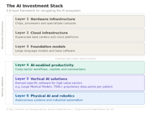
🎙️ Al walks through the full framework, including valuation, timeline shifts, and next-gen cognitive systems, on episode 125 of the Tsinghua to Wall Street podcast:
👉 https://www.youtube.com/watch?v=dbpNhMCENeY
What happens when you find another market for your product?
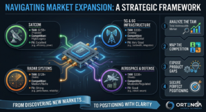
As soon as you find it, a strategic chain reaction triggers that replaces guesswork with data-driven growth:
📊 1. Analyze the TAM
- Define total revenue potential.
- Set concrete percentage goals.
⚔️ 2. Map the Competition
- Track active industry rivals.
- Bench-test against theirs.
💡 3. Expose Product Gaps
- Uncover your unfair advantages.
- Pinpoint critical technical disadvantages.
🎯 4. Secure Perfect Positioning
- Gain total market visibility.
- See clearly where your product should be to win.
One technology. Many markets. The right market changes everything.
But for complex hardware like RF amplifiers, generic market maps fail. You need custom system-level visibility tailored to your exact silicon constraints and thermal limits.
We help engineering teams bridge the gap between technical reality and market dominance. Let’s find exactly where your technology wins.
👉 Submit a Project Discovery Request here: https://ortenga.net/project-discovery-request/
The ADC Met Hardware Specifications, But Not System-Level Requirements
A receiver platform relied on advanced time-interleaved ADCs to achieve wideband coverage.
The hardware team conducted a thorough evaluation process spanning more than 12 months before selecting an ADC that met the documented hardware requirements. The device satisfied the required bandwidth, dynamic range, and performance metrics. Significant component expertise was involved in the evaluation, vendor engagement, trade-off analysis, and final down-selection. Purchase orders were placed, schedules were established, and the program moved forward.
From a hardware perspective, the decision appeared well-founded.
Months later, during system integration, customer complaints began to emerge.
The issue was eventually traced back to the ADC architecture.
The surprising part was that the ADC had not failed.
It was operating within its documented hardware specifications.
The problem was that the hardware requirements used during the down-selection process did not fully capture the system-level requirements that emerged when multiple ADCs, calibration mechanisms, and signal-processing algorithms operated together within the complete receiver architecture.
The ADC met hardware specifications.
The system did not meet system-level requirements.
A Thorough Evaluation Still Missed the Problem
This was not a rushed decision.
The ADC selection process involved more than a year of evaluation, analysis, and review. Experienced hardware engineers assessed performance metrics, calibration requirements, temperature drift behavior, vendor support, and implementation trade-offs.
The selected ADC satisfied the documented requirements.
Yet a critical issue remained undiscovered.
Why?
Because the missing requirement did not exist at the component level.
It existed at the system level.
The receiver relied on algorithms that consumed data from multiple ADCs operating together. The performance of those algorithms depended not only on the behavior of individual ADCs, but also on the interaction between:
- Multiple ADCs
- Calibration mechanisms
- Synchronization behavior
- Residual mismatch errors
- Temperature drift
- Long-term operational stability
These interactions were not fully represented during the hardware down-selection process.
As a result, the ADC selection was treated primarily as a hardware engineering decision when it was actually a system-level engineering decision.
The Missing Stakeholder
The organization assumed that hardware engineering could independently define the hardware requirements and perform the hardware down-selection.
This assumption is common.
After all, who better to define ADC requirements than ADC experts?
The challenge is that some requirements are not owned by a single engineering discipline.
In this case, algorithm performance depended on behaviors that were not obvious from a component-level perspective. The hardware team could evaluate the ADC against documented hardware requirements, but the system-level implications only became visible when hardware and algorithms were integrated together.
The missing stakeholder was not additional ADC expertise.
The missing stakeholder was system-level engineering.
A system-level audit would have asked questions such as:
- How sensitive are the algorithms to residual ADC mismatch?
- How does calibration drift affect long-term accuracy?
- What assumptions are the algorithms making about multiple ADCs operating together?
- Which customer-level performance metrics depend on ADC behavior?
Those questions sit at the boundary between hardware and algorithms.
They are system questions.
When the Discovery Occurred
Unfortunately, the discovery did not occur during the evaluation phase.
It did not occur during procurement.
It did not occur until hardware and algorithms were integrated into the complete system.
Only then did the impact become visible.
By that point:
- Hardware had already been purchased.
- Significant financial commitments had been made.
- Development schedules had been established.
- Customer expectations had been set.
The engineering team no longer had the freedom to ask:
“What is the best architecture for this application?”
Instead, they were forced to ask:
“How do we make the current architecture work?”
Those are fundamentally different engineering situations.
One optimizes the solution.
The other mitigates the consequences of earlier assumptions.
The Cost of Late Discovery
The technical challenge was significant.
The business challenge was even greater.
Once hardware commitments had been made, changing direction was no longer practical from either a schedule or cost perspective.
The organization had effectively lost decision freedom.
Before the purchase order:
- Multiple architectural options existed.
- Requirements could still be refined.
- Hardware choices could still be reconsidered.
After the purchase order:
- Alternatives became expensive.
- Schedule pressure increased.
- Engineering effort shifted from optimization to mitigation.
The issue did not become expensive when the customer complained.
It became expensive the moment the organization committed to a design direction before the system-level requirements were fully understood.
A Pattern We Have Observed Repeatedly
This experience is not unique to ADCs.
We have observed similar situations across:
- Antenna systems
- ASIC developments
- Signal-processing algorithms
- Radar systems
- SATCOM platforms
- Multi-disciplinary engineering programs
The pattern is remarkably consistent.
Individual teams make sound decisions within their respective domains.
The hardware team optimizes hardware.
The algorithm team optimizes algorithms.
The software team optimizes software.
The challenge emerges at the boundaries between those domains.
Those boundaries are where hidden assumptions often reside.
Unfortunately, they are also where the most expensive discoveries are made.
The Observation That Led to the ORTENGA Engineering Risk & RoI Blueprint
Repeated experiences like these led to the development of the ORTENGA Engineering Risk & RoI Blueprint:
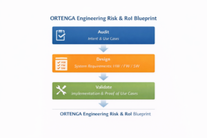
Audit → Design → Validate
Most organizations perform Design and Validate.
The missing step is often Audit.
The purpose of Audit is not to design the solution.
Its purpose is to identify:
- Hidden assumptions
- Cross-domain dependencies
- System-level constraints
- Stakeholder requirements
- Technical risks
- Business risks
- Validation criteria
before major engineering and financial commitments are made.
Audit ensures that system-level intent is understood before requirements are allocated to hardware, firmware, software, and algorithms.
Design then translates that audited intent into executable engineering requirements.
Validation confirms that the implemented system performs as intended.
When this sequence is followed, critical discoveries occur before commitment.
When it is not, critical discoveries often occur during integration, when correction becomes dramatically more expensive.
Conclusion
The ADC met its hardware specifications.
The customer still complained.
Not because the component failed.
Not because the hardware team lacked expertise.
Not because the evaluation process lacked rigor.
The issue emerged because system-level requirements were not fully represented during a decision that was ultimately system-level in nature.
The critical requirements were not hidden inside the ADC.
They were hidden within the interaction between hardware, algorithms, and customer-level performance objectives.
By the time those requirements became visible, the organization had already committed to a design direction.
This experience reinforced a lesson we have observed repeatedly across complex engineering programs:
Many engineering failures are not implementation failures.
They are discovery failures.
Critical system-level information is discovered after major commitments have already been made.
Learn More
This case study reflects the core principles described in the ORTENGA Engineering Risk & RoI Blueprint:
How Product Development Starts—and Why It Fails
The white paper explains how the Audit → Design → Validate methodology helps identify hidden assumptions, cross-domain dependencies, and system-level risks before major commitments are made.
Explore the white papers:
Funding accelerates the cost of market uncertainty.
Most founders don’t feel it until the burn rate does the math for them.
You just closed your round. Congratulations.
Now you’re hiring.
Sales lead. Applications engineer. Business development. Maybe a marketing director.
Each offer letter is a monthly commitment — signed before you’ve confirmed which market you’re actually targeting.
That’s not momentum. That’s overhead with a headcount report attached.
We’ve seen high-tech startups raise serious money, build capable teams, and spend 18 months discovering that the markets they assumed were obvious weren’t obvious at all. The people they hired were optimized for a customer that never materialized.
Every hire made without market direction doesn’t accelerate your path. It raises the cost of being wrong.
Headcount is not a substitute for scope.
The first question isn’t “who do we need?”
It’s “which market are we actually targeting — and why does our product win there?”
Answer that first. Then hire precisely against the answer.
If you’re in active hiring mode, it’s worth understanding what’s at stake first.
🔗 Explore the risk → https://ortenga.net/project-discovery-request/