Antenna System Module (ASM) Engineering — From Electromagnetic Architecture to Deployment Reality
ORTENGA supports Antenna System Module (ASM) engineering programs across SATCOM,
radar, wireless infrastructure, autonomous systems, and next-generation RF platforms.
We help organizations translate deployment realities, system constraints,
and business objectives into executable ASM architectures and validated
electromagnetic performance.
Modern ASM performance is no longer determined by antenna geometry alone.
It depends on the interaction between electromagnetic behavior,
semiconductor architecture, packaging, algorithms, thermal constraints,
deployment conditions, subsystem integration, and operational realization.
System Before Antenna.
Architecture Before Geometry.
Validation Before Scale.
Why Programs Realize Failure Late
Many RF and ASM programs appear technically viable during early development.
The underlying issues often surface much later:
- during subsystem integration
- deployment testing
- thermal characterization
- fabrication
- calibration
- field operation
- or customer deployment
By that stage, capital has been spent, schedules have shifted,
subsystem dependencies have formed, and realization flexibility
has already narrowed.
The root cause is frequently upstream:
- undefined deployment assumptions
- incorrect system architecture
- disconnected RF and algorithm assumptions
- packaging conflicts
- thermal and power limitations
- incomplete understanding of the operating environment
- lack of coordination across hardware, firmware, mechanical, and system-level behaviors
As a result, organizations often optimize ASM performance in isolation
while the complete deployed system underperforms.
Execution progress validates that the organization is building the system efficiently.
It does not necessarily validate that the organization is building the correct system
against the original business objectives and deployment realities established during Audit.
The issue is rarely the antenna alone.
The issue is that ASM engineering is often treated as an isolated
electromagnetic task instead of a system-level architectural discipline
tied to deployment realities, operational behavior, and business objectives.
The ORTENGA Engineering Risk & RoI Blueprint
Complex engineering programs require more than implementation progress.
They require continuous alignment between deployment realities,
system intent, realization architecture, implementation execution,
and operational validation.
ORTENGA applies a structured Audit → Design → Validate methodology
to reduce hidden realization risk before fabrication, deployment,
and investment lock-in occur.
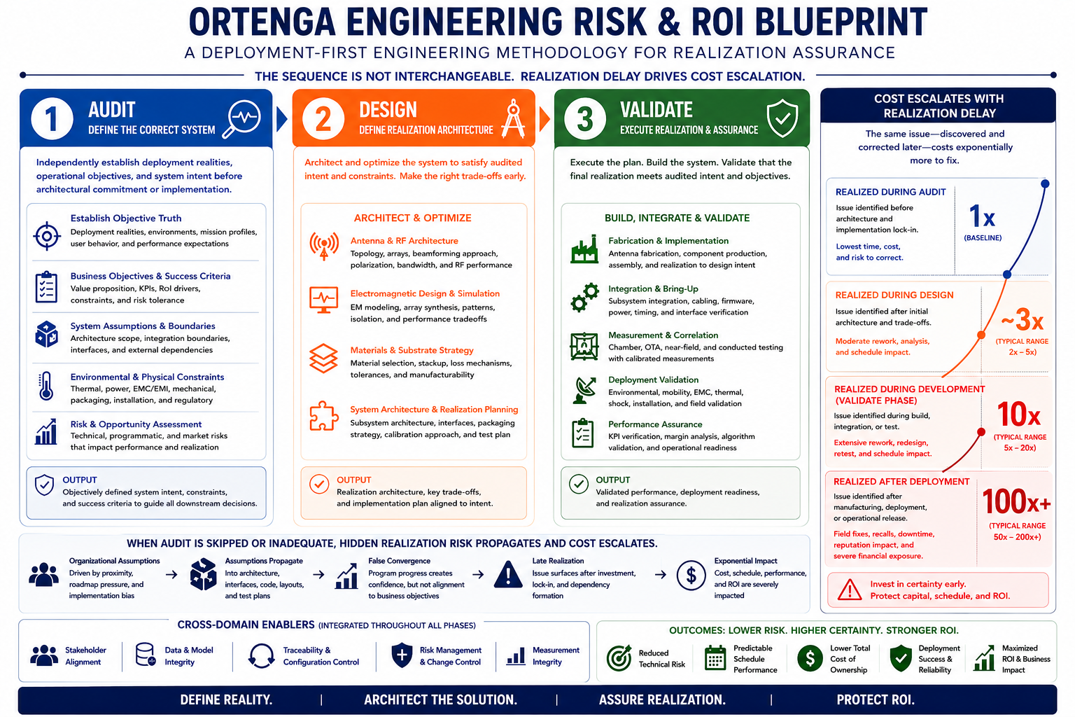
Audit
Independently establish deployment realities,
operational objectives, business constraints,
and system intent before realization momentum begins.
Define the correct system before downstream realization risk escalates.
Design
Architect and optimize the ASM through electromagnetic simulations,
trade studies, realization planning, subsystem coordination,
and implementation-aware engineering.
Establish realization-ready architecture before fabrication and deployment begin.
Validate
Execute fabrication, integration, chamber measurements,
OTA validation, deployment verification,
and operational readiness assurance.
Confirm the realized system performs correctly within deployment reality.
Skipping independent upstream Audit does not eliminate risk.
It transfers risk downstream into realization,
integration, deployment, schedule, and RoI exposure —
where the cost and complexity of correction increase dramatically.
Why Antenna System Module (ASM)?
Every radio and radar system fundamentally contains four major functional domains:
- Antenna System Module (ASM)
- Front-End Module (FEM)
- Transceiver Module (TRM)
- Baseband Module (BBM)
In some architectures these functions are implemented as physically separate modules.
In others, they may be highly integrated into a single package,
subsystem, or semiconductor device.
However, regardless of implementation approach,
each functional domain performs distinct system responsibilities
that directly impact operational performance.
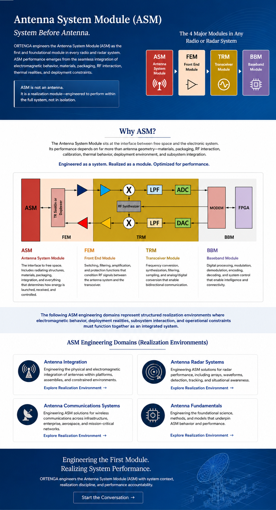
ORTENGA uses the term Antenna System Module (ASM) to emphasize
that modern antenna performance is no longer determined by antenna geometry alone.
ASM performance emerges from the interaction between:
- electromagnetic behavior
- packaging
- materials
- RF interactions
- algorithms
- thermal constraints
- deployment realities
- subsystem integration
- operational environments
The antenna is therefore no longer an isolated structure.
It is a realization subsystem operating within the larger
radio or radar architecture.
Antenna System Module (ASM) Engineering Realizations
The following ASM engineering realizations represent structured environments
where electromagnetic behavior, deployment realities, subsystem interaction,
and operational constraints must function together as an integrated system.
Antenna Integration
System-level antenna realization, environmental coupling,
deployment interaction, and realization-aware integration.
Antenna Arrays and Beamforming
Distributed apertures, beam steering,
mutual coupling, sidelobe control,
and array realization systems.
Antenna in Package
Antenna-package interaction, RF/silicon integration,
tuners, matching structures,
and implementation-aware realization.
gNB / 6G Infrastructure
Massive MIMO, distributed RF architectures,
mmWave deployment realities,
and next-generation wireless realization.
Antenna Radar Systems
Radar apertures, slotted waveguides,
horn structures, circular polarization,
and sensing-oriented realization.
Autonomous and Smart Systems Antenna
AI-assisted antenna systems,
adaptive electromagnetic behavior,
and intelligent RF environments.
Emerging Antenna Topologies
Fractal structures, sinuous antennas,
unconventional geometries,
and future antenna realization concepts.
Antenna Fundamentals
Electromagnetic radiation, resonance,
miniaturization, bandwidth,
and foundational antenna engineering principles.
Structured Engineering Execution
Complex ASM and RF programs involve tightly coupled interactions
between deployment realities, realization architecture,
subsystem integration, schedule constraints,
and operational objectives.
Effective execution therefore requires structured alignment between:
- business intent
- system definition
- realization architecture
- implementation execution
- deployment validation
Ad-hoc execution breaks realization alignment,
increasing investment and schedule exposure
and ultimately eroding RoI.
ORTENGA operates through structured Statements of Work
designed to preserve realization alignment across architecture,
implementation, fabrication, and deployment validation.
Engineering Clarity Before Realization Risk Escalates
Whether evaluating a new ASM architecture,
recovering a drifting RF program,
validating deployment readiness,
or aligning implementation with operational objectives,
ORTENGA provides structured engineering leadership
from system definition through realization
and deployment validation.
The objective is not simply engineering progress.
The objective is realization alignment between deployment realities,
system architecture, implementation execution,
and intended business outcomes.