- Antenna in Package, AiP
- Emerging 6G Technologies
- Cellular Architecture will be Replaced with Cell Free Architecture in 6G
- Rayleigh vs. Rician Fading
- 6G Multi Antenna Technology
- From Small Cells to Cell-Free Networks
- Talking and Listening on the Same Spectrum
- Why OFDM Survived 5G And Why Radio Above 100 GHz May Require New Waveforms
This Forum will be posting related contents and welcome business professionals, technologists, engineers, or scientists for introducing relating materials.
Inquire: info@ortenga.net
Antenna in Package, AiP
As FCC allocating higher frequency bands for 5G, it is expected that 6G will be sub Terahertz frequency bands starting at 125GHz.
At these frequencies the wavelength is so small and Ohmic losses are so high per unit length that it makes sense to integrate Antenna in Package, AiP, or even Antenna integrated with Front End Module silicon.
Therefore, 6G Technology will be about radio front end which is integrated within semiconductor technology.
Semiconductor technology and its capabilities will be centered and complete communication systems will be in order of 2”x2” at the most if not smaller.
Partner with ORTENGA in your next generation Antenna design and development.
Emerging 6G Technologies
There are many articles about what 6G brings and enable for Terrestrial communications.
Here are some of obvious changes which you should expect.
- mmW frequencies reduce the component size
- hence, mmW frequencies enable more integrations
- off chip passive components can be integrated onto the chip or at least onto the package
- Passive components, e.g., Antenna, Filter, Transmission Line, Stub, Coupler, etc.
- Active components would be much more sophisticated
- Active components, e.g., ADC and DAC
- ADC and DAC would be broadband using interleaving technology
- Broadband ADC and DAC would enable SDR architecture
Businesses which plan according with vision for the future market, end up winning new market.
Partner with ORTENGA to define your new product line.
Cellular Architecture will be Replaced with Cell Free Architecture in 6G
Wireless Cellular Network has expanded over the past two decades exponentially and enabled global populations in all contents with access to online access to internet and more importantly to each other.
The impact is significant by any measured metrics from technical to social and economic evolution.
You could post a picture online for your loved ones across the glob and they can enjoy that picture in only seconds from the moment you took that picture.
You even can share movie of your birthday, wedding, and anything that is important to you to virtually share that moment with the same wireless cellular network.
All that technical infrastructure built over the past two decades are about to go through another major technical wireless evolution.
To better understand the need for another major shift in the wireless infrastructure, we need to understand the existing wireless cellular network based on providing some minimum quality of service and throughput for anyone in the network.
Although that was significant major improvement compared to legacy wired infrastructure, that would not be competitive for future markets.
6G market would require much better datarate and quality of service to address AI, XR, and interpersonal connectivity.
To learn more about Cell Free Architecture follow Professor Emil Bjornson who is the pioneer in that area.
ORTENGA works with client and stakeholders to identify goals and deliverables of the project.
ORTENGA helps businesses to identify required technical features to realize their business goals.
Partner ORTENGA in your next product concept, design, and development to realize that business goal.
ORTENGA has seasoned engineering from Autonomous Automotive, SATCOM, radar, Smart City, WiFi, and Mobile Terrestrial Radio Communications System industries in Antenna, ASIC, Algorithm, HW, FW, and SW engineering disciplines.
Rayleigh vs. Rician Fading
Terrestrial Radio Link analysis consists of Line of Sight, Large Scale fading, Small Scale fading depending on the frequency, and Atmospheric Loss.
Large Scale Fading
Large scale fading refers to environment where the radio signal bounces of objects that are “much larger” than operating wavelength.
Large Scale fading is deterministic and it’s part of the Radio Link Budget Analysis.
Small Scale Fading
Small scale fading refers to fading environment where the radio signal bounces of objects that are “smaller” than operating wavelength.
Small Scale fading is random in nature, yet it can be introduced in the Radio Link Budget via Fade Margin. The fade margin represents the level of robustness for the Radio Link.
Small scale fading is typically modeled either by Rayleigh or Rician probability distribution function profile.
The radio signal is modulated by fading profile.
Rayleigh model reflects a channel with many multipath between transmitter and receiver which occurs in many Terrestrial radio applications, such as Cellular, i.e. 4G/5G, and WiFi, i.e. 802.11.
The probability distribution function describes the probability of occurrence as a function of radio signal envelope. The larger number of multipath between the transmitter and the receiver, the more spread the envelope radio signal envelope profile.
Rician model reflects a channel with one dominant, aka specular, path between the transmitter and the receiver. Obviously, the radio signal envelope for dominant path occurs with higher or distinct probability with respect to other multipath.
Rician model approaches Rayleigh probability density function as the dominant path becomes less and less in reflecting signal strength, therefore less pronounced.
In the case of 5G and WiFi applications, appropriate large and small scale fading terms must be included in the Radio Link Budget for robust radio design.
Partner with ORTENGA to analyze the Link Budget for your radio application and down select vendor/component for the design of new project.
6G Multi Antenna Technology
6G would follow 5G multi antenna technology with some changes.
5G mmW has not been universally accepted terrestrial radio communication platform of choice.
The reason for 5G mmW delayed implementation is capital cost, CAPEX entrance threshold. The cost of beamforming ASIC and mmW antennas are BOM differentiators compare to 4G and previous terrestrial radio communication 3GPP standards.
The number of gNB would increase in 6G as the cellular area is function of electrical length. Another way put, as the frequency increases, the wavelength decreases, and the cell area in wavelength remain the same.
Partner with ORTENGA in Radio Communication System network design and development.
From Small Cells to Cell-Free Networks
Why Wireless Architecture Is Becoming a Distributed Mosaic of Radios
For decades, wireless networks have been designed around a simple assumption: a small number of powerful towers radiate signals across large geographic areas.
This architecture enabled the rapid global expansion of cellular communication, connecting billions of people and transforming how societies share information, communicate, and interact.
Today a photo taken anywhere in the world can be shared instantly with friends and family across continents. Videos of personal milestones—birthdays, weddings, and important life events—can be transmitted globally within seconds.
But the forces shaping the next generation of wireless systems are fundamentally different.
Rising data demand, higher operating frequencies, and new applications such as AI-enabled services and extended reality are pushing wireless infrastructure toward a new model. Rather than relying on a few high-power towers, future networks will increasingly consist of large numbers of low-power radios distributed throughout the environment.
In this emerging architecture, connectivity will be delivered through a dense mosaic of radios embedded in cities, buildings, vehicles, and public infrastructure.
The Macro Cell Era
Traditional wireless networks were built around large macro cells.
A relatively small number of high-power base stations, typically mounted on towers or tall structures, provided wide-area coverage. These base stations often used three-sector antennas to divide coverage into large geographic regions.
This architecture prioritized broad geographic coverage with minimal infrastructure, which was appropriate for the early generations of cellular communication.
However, as wireless demand increased, the limitations of this approach became more apparent.
The Shift Toward Small Cells
As wireless systems move toward higher frequencies and higher data capacity, the propagation characteristics of radio signals change. Signals experience greater attenuation when passing through buildings, walls, and other obstacles.
At the same time, the demand for higher data rates continues to grow rapidly.
To address these challenges, network architectures are evolving toward dense deployments of small cells placed closer to users.
Unlike traditional macro towers, small cells operate with:
- lower transmit power
- shorter wavelengths (higher frequencies)
- directional or beam-steered antennas
- smaller coverage areas
Rather than relying on a few large towers, future wireless networks will increasingly consist of many low-power access points embedded throughout the environment.
This creates what can be described as a mosaic of small cells woven into the environment.
Figure 1 — Dense Mosaic of Small Cells
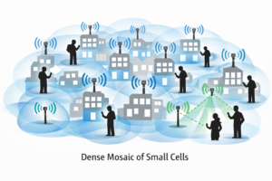
The figure illustrates how dense small-cell deployments create overlapping coverage areas distributed throughout urban environments.
The Next Evolution: Cell-Free Architecture
Even the concept of “cells” may eventually disappear.
Future wireless systems, particularly those envisioned for 6G, are exploring cell-free architectures. In this approach, a large number of distributed access points cooperate to serve users simultaneously rather than dividing coverage into separate cells.
Instead of connecting to a single base station, a user device may be served by multiple coordinated radios distributed across the network.
This architecture can significantly improve:
- network capacity
- service uniformity
- reliability
- spectral efficiency
The network becomes user-centric rather than cell-centric, effectively eliminating the traditional boundaries between cells.
Much of the pioneering research in this area has been led by Professor Emil Björnson, whose work on Cell-Free Massive MIMO helped establish the theoretical foundations of this emerging architecture.
A Distributed Wireless Future
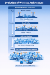
The evolution of wireless infrastructure can be viewed as a progression:
Macro Cell Networks
↓
Dense Small Cell Deployments
↓
Cell-Free Distributed Radio Systems
Figure 2 — Evolution of Wireless Architecture
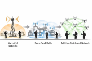 The diagram illustrates how wireless infrastructure is evolving from tower-centric networks to distributed radio systems.
Each stage moves wireless infrastructure closer to users while increasing coordination between radios.
In the long term, wireless connectivity may resemble a distributed fabric of radios embedded throughout cities, buildings, vehicles, and public spaces.
ORTENGA Perspective
Major advances in wireless technology rarely come from incremental improvements in radio components alone. They are often driven by architectural shifts in how networks are designed and deployed.
The transition from macro cellular networks to dense small-cell deployments—and ultimately toward cell-free distributed radio systems—represents one of the most significant architectural evolutions in the history of wireless communication.
As wireless infrastructure becomes more distributed, the complexity of designing and integrating these systems increases significantly. Successful deployment will require coordinated innovation across multiple engineering disciplines, including antennas, semiconductor technology, signal processing algorithms, hardware platforms, and software-defined networking.
Organizations that understand this architectural shift early will be better positioned to design scalable wireless platforms for the next generation of connectivity.
ORTENGA works with clients and stakeholders to identify system objectives, define technical architectures, and translate emerging technologies into practical engineering solutions.
With experience spanning autonomous automotive, SATCOM, radar, smart city infrastructure, Wi-Fi, and terrestrial mobile communications, ORTENGA brings multidisciplinary expertise across antenna, ASIC, algorithm, hardware, firmware, and software engineering.
Partner with ORTENGA in your next product concept, design, and development to transform innovative ideas into scalable wireless systems.
The wireless network of the future will not be defined by towers — it will be defined by a distributed fabric of coordinated radios surrounding the user.
Talking and Listening on the Same Spectrum
Full-Duplex Radios and the Rise of Cell-Free Wireless Networks
For decades, wireless networks have been designed around a simple assumption: a relatively small number of powerful towers radiate signals across large geographic areas.
This architecture enabled the rapid global expansion of cellular communication, connecting billions of people and transforming how societies share information, communicate, and interact.
Today a photo taken anywhere in the world can be shared instantly with friends and family across continents. Videos of personal milestones—birthdays, weddings, and important life events—can be transmitted globally within seconds.
But the forces shaping the next generation of wireless systems are fundamentally different.
Rising data demand, higher operating frequencies, and new applications such as AI-enabled services and extended reality are pushing wireless infrastructure toward a new model. Rather than relying on a few high-power towers, future networks will increasingly consist of large numbers of low-power radios distributed throughout the environment.
In this emerging architecture, connectivity will be delivered through a dense mosaic of radios embedded in cities, buildings, vehicles, and public infrastructure.
Figure 1 — Evolution of Wireless Architecture
The figure illustrates how wireless infrastructure is evolving from tower-centric macro cells toward dense deployments of distributed radios. As transmit power decreases and radios become more coordinated, technologies such as full-duplex communication may become increasingly practical.
Key Insight
The evolution of wireless networks is not only about adding more radios. It is about changing how those radios operate.
As networks move from a few high-power towers to dense deployments of low-power distributed radios, the physical barriers that once prevented simultaneous transmit and receive begin to relax.
Lower transmit power and shorter communication distances make self-interference cancellation more achievable, opening the door to full-duplex radios operating on the same spectrum.
In this sense, the transition to cell-free wireless architecture may also enable the next major leap in spectral efficiency: radios that can talk and listen on the same frequency at the same time.
The Macro Cell Era
Traditional wireless networks were built around large macro cells.
A relatively small number of high-power base stations, typically mounted on towers or tall structures, provided wide-area coverage. These base stations often used sectorized antennas to divide coverage into large geographic regions.
This architecture prioritized broad geographic coverage with minimal infrastructure, which was appropriate for the early generations of cellular communication.
However, as wireless demand increased, the limitations of this approach became more apparent.
The Shift Toward Small Cells
As wireless systems move toward higher frequencies and higher data capacity, the propagation characteristics of radio signals change. Signals experience greater attenuation when passing through buildings, walls, and other obstacles.
At the same time, demand for higher data rates continues to grow rapidly.
To address these challenges, network architectures are evolving toward dense deployments of small cells placed closer to users.
Unlike traditional macro towers, small cells operate with:
- lower transmit power
- higher operating frequencies
- directional or beam-steered antennas
- smaller coverage areas
Rather than relying on a few large towers, future wireless networks increasingly consist of many low-power access points embedded throughout the environment.
This creates what can be described as a mosaic of radios woven into the environment.
The Next Evolution: Cell-Free Architecture
Even the concept of “cells” may eventually disappear.
Future wireless systems, particularly those envisioned for 6G, are exploring cell-free architectures, where a large number of distributed access points cooperate to serve users simultaneously rather than dividing coverage into separate cells.
Instead of connecting to a single base station, a user device may be served by multiple coordinated radios distributed across the network.
This architecture can significantly improve:
- network capacity
- service uniformity
- reliability
- spectral efficiency
The network becomes user-centric rather than cell-centric, effectively eliminating the traditional boundaries between cells.
Much of the pioneering research in this area has been led by Professor Emil Björnson, whose work on Cell-Free Massive MIMO helped establish the theoretical foundations of this emerging architecture.
Where Full-Duplex Radios May Fit
This distributed architecture also creates an environment where full-duplex radios become more practical.
In conventional macro-cell systems, base stations transmit at very high power levels. The resulting transmitter leakage into the receiver can exceed the desired signal by over 100 dB, making simultaneous transmit and receive extremely difficult.
However, in dense small-cell and cell-free networks, transmit power levels are much lower.
Lower transmit power reduces the dynamic range challenge and makes self-interference cancellation more feasible.
Figure 2 — The Dynamic Range Challenge in Full-Duplex Radios
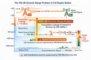
In full-duplex radios, the transmitted signal can be more than 100 million times stronger than the desired received signal. Without sufficient suppression, transmitter leakage overwhelms the receiver.
Because of this extreme dynamic range, full-duplex radios typically rely on multiple layers of interference suppression.
Figure 3 — Layered Self-Interference Cancellation
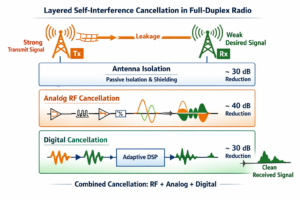
Practical full-duplex radios rely on several layers of suppression:
- antenna isolation
- analog RF cancellation
- digital baseband cancellation
Combined suppression from these techniques may exceed 100 dB, allowing the receiver to detect extremely weak incoming signals while the transmitter operates simultaneously on the same spectrum.
A Distributed Wireless Fabric
The evolution of wireless infrastructure can therefore be viewed as a progression:
Macro Cell Networks
↓
Dense Small Cell Deployments
↓
Cell-Free Distributed Radio Systems
↓
Potential Full-Duplex Distributed Radios
In the long term, wireless connectivity may resemble a distributed fabric of coordinated radios embedded throughout cities, buildings, vehicles, and infrastructure.
ORTENGA Perspective
Major advances in wireless technology rarely come from incremental improvements in radio components alone. They are often driven by architectural shifts in how systems are designed and deployed.
The transition from macro cellular networks to dense small-cell deployments—and ultimately toward cell-free distributed radio systems with advanced capabilities such as full-duplex communication—represents one of the most significant architectural evolutions in the history of wireless communication.
As wireless infrastructure becomes more distributed, the complexity of designing and integrating these systems increases significantly.
Successful deployment will require coordinated innovation across multiple engineering disciplines, including:
- antennas
- semiconductor technology
- signal processing algorithms
- RF hardware platforms
- distributed software architectures
ORTENGA works with clients and stakeholders to identify system objectives, define technical architectures, and translate emerging technologies into practical engineering solutions.
The wireless network of the future will not be defined by towers — it will be defined by a distributed fabric of coordinated radios surrounding the user.
Why OFDM Survived 5G And Why Radio Above 100 GHz May Require New Waveforms
For more than two decades, Orthogonal Frequency Division Multiplexing (OFDM) has been the dominant waveform in modern wireless communication systems. It powers technologies ranging from LTE to 5G New Radio standardized by the 3rd Generation Partnership Project.
During the development of 5G, several alternative waveforms were proposed, including Filter Bank Multi-Carrier (FBMC), Generalized Frequency Division Multiplexing (GFDM), and Universal Filtered Multi-Carrier (UFMC). Each attempted to address perceived limitations of OFDM such as spectral leakage, synchronization sensitivity, or Peak-to-Average Power Ratio (PAPR).
Yet despite these proposals, OFDM ultimately remained the foundation of the 5G air interface.
The reason is straightforward: within the frequency ranges used by 5G, OFDM represents the most practical engineering compromise between performance, complexity, and ecosystem maturity.
Why OFDM Survived 5G
Several characteristics allowed OFDM to remain the dominant waveform in 5G systems.
Efficient Multipath Equalization
OFDM divides a wideband channel into many narrow subcarriers. Each subcarrier experiences relatively flat fading, allowing equalization to be performed using simple single-tap frequency-domain processing.
This dramatically reduces receiver complexity for broadband wireless systems.
Natural Compatibility with Massive MIMO
Massive MIMO is one of the central capacity drivers in modern cellular networks.
OFDM integrates naturally with MIMO processing because channel estimation and precoding can be performed independently on each subcarrier. This simplifies spatial multiplexing and beamforming.
Mature Semiconductor Ecosystem
By the time 5G was standardized, OFDM had already been widely deployed in:
- cellular systems
- broadband wireless
- Wi-Fi networks.
This mature ecosystem significantly reduced implementation risk for the industry.
Flexible Numerology
5G enhanced OFDM rather than replacing it by introducing scalable subcarrier spacing, often referred to as numerology.
Typical spacings include:
- 15 kHz
- 30 kHz
- 60 kHz
- 120 kHz
This flexibility allows OFDM to operate across frequencies ranging from traditional cellular spectrum to millimeter-wave bands.
Figure 1 — OFDM Strengths vs Limitations
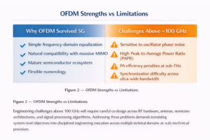
This comparison illustrates why OFDM remained the practical waveform choice for 5G systems while also highlighting the challenges that may emerge at much higher frequencies.
The strengths of OFDM—simple equalization, strong MIMO compatibility, and a mature ecosystem—made it a natural foundation for 5G.
However, several characteristics become increasingly challenging as systems move toward sub-THz frequencies, including sensitivity to oscillator phase noise, high PAPR interacting with limited PA efficiency, and synchronization across extremely wide bandwidths.
Why Communication Above 100 GHz Is Different
Many RF limitations that once constrained wireless communication in lower frequency bands have become well-understood engineering tradeoffs.
Advances in semiconductor technology, oscillator design, amplifier linearization, and synchronization algorithms have made these challenges manageable.
However, communication above 100 GHz (sub-THz) introduces a new generation of challenges that remain open engineering problems.
Oscillator Phase Noise
Oscillator phase noise increases with carrier frequency.
At sub-THz frequencies, maintaining the frequency stability required for tightly spaced OFDM subcarriers becomes significantly more difficult. Phase noise spreads energy across neighboring subcarriers, creating inter-carrier interference.
Power Amplifier Efficiency
Power amplifiers operating above 100 GHz currently exhibit:
- very low efficiency
- limited output power
- strong nonlinear behavior.
Because OFDM signals inherently have high Peak-to-Average Power Ratio (PAPR), transmitters must operate with significant power back-off. At sub-THz frequencies, where RF power is already scarce, this inefficiency becomes a major constraint.
Ultra-Wideband Synchronization
Future systems above 100 GHz may operate across tens of gigahertz of bandwidth.
Maintaining precise timing and frequency synchronization across such wide bandwidths is significantly more challenging than in today’s cellular systems.
RF Front-End Integration
Packaging, antenna integration, and RF front-end architectures become increasingly complex at sub-THz frequencies.
These hardware constraints directly influence waveform design because they affect:
- linearity
- bandwidth
- phase stability
- synchronization performance.
Figure 2 — Engineering Constraints vs Frequency
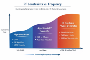
This figure illustrates how the dominant engineering constraints shift as wireless systems move toward higher frequencies.
At traditional cellular frequencies, system performance is largely determined by signal processing algorithms and channel equalization techniques.
In millimeter-wave systems, waveform design becomes a balance between signal processing and RF hardware limitations.
Beyond roughly 100 GHz, RF hardware physics increasingly dominates system behavior.
Key Insight
The RF limitations that once constrained wireless communication in lower bands have largely become solved engineering problems.
However, communication above 100 GHz introduces a new generation of constraints that are not yet fully solved at scale.
Because waveform design is tightly coupled to RF hardware behavior, these unresolved challenges may eventually require new waveform architectures beyond OFDM.
OFDM survived 5G not because it is perfect, but because decades of engineering turned its limitations into well-understood design tradeoffs.
Communication above 100 GHz may require new waveforms not because OFDM failed, but because the RF problems in this spectrum regime have not yet been solved.
ORTENGA Perspective
Engineering challenges above 100 GHz require careful co-design across RF hardware, antennas, semiconductor architectures, and signal processing algorithms. Addressing these problems demands translating system-level objectives into disciplined engineering execution across multiple technical domains.
ORTENGA is an elite engineering network of antenna, ASIC, and algorithm specialists helping clients execute complex Statements of Work predictably—on budget, on schedule, and with technical precision.
To manage technical risk and ensure predictable execution, ORTENGA follows the:
ORTENGA Engineering Risk & RoI Blueprint
Audit | Design | Validate
- Audit – clarify business objectives, use cases, and system constraints
- Design – translate those objectives into structured system architectures and engineering requirements
- Validate – ensure the system performs reliably for the intended use cases
This disciplined approach helps organizations convert ambitious technology goals into deployable engineering solutions while managing technical risk and development complexity.