- Emergency Vehicles in Smart City
- Drone Technology
- NB-IoT Applications and Classifications
- V2X Connectivity
- Smart Cities Are System Architectures, Not Mobile Apps
- Wireless Power Transfer: It’s Not About RF — It’s About Wavelength Discipline
The Smart City Concept has been taking shape for the past 15 years.
The concept is intelligent connectivity between commercial and public facilities to your handheld device, UE.
As you walk in downtown area, you will be able to access information regarding restaurants, bus or train schedules, post office, etc. at your request with much more user friendly applications. You will be able to ask question of your UE and the response will pop up or voice to tell you about your destination, the ratings, wait time, menu, etc.
If you have a destination via train, your UE will make you aware of timeline, location, and other options to get you there, think of like Uber, Lyft, Amtrak applications are combined with much more info and extremely easy to use.
Currently, Barcelona is number 1 smart city, followed by Munich.
This Forum will be posting related contents and welcome technologist, engineers, scientists for introducing relating materials.
Inquire: info@ortenga.net
Emergency Vehicles in Smart City
Any city quality of life can be measured by its First Responders’ services.
Currently, the dispatchers are the conduit between Emergency Vehicles and the person in need until the First Responders arrive at the scene.
In Smart City that would change, as soon as the person in need contact First Responders, i.e., Fire Department, they can be directly connected to the First Responders team leader heading to the scene.
That connectivity enables the First Responders to start their work even before they arrive at scene.
Paramedic is on the way and making the first introductions in advance. The person in need is already in good hand and describing the nature of emergency s/he is facing.
The time of arrival, the specifics of neighborhood directions, etc. are all handled directly between the service provider and the user.
That type of service requires direct and intelligent 1connectivity between Emergency Vehicle and third-party mobile device.
Partner with ORTENGA to define your product in such a way that fits in Smart City.
Drone Technology
Drone technology is used for many new commercial applications.
Many of the commercial applications can be lumped into Smart City application.
In rural area, Drones will be used in agriculture industry.
Highways control will be managed by Drones as well.
The advanced of semiconductor technologies and particularly ASIC developments have enabled many out of box alternative solutions to legacy products.
ORTENGA helps businesses to identify required technical features to realize their business goals.
Partner ORTENGA in your next product concept, design, and development to realize that business goal.
ORTENGA has seasoned engineering from Autonomous Automotive, SATCOM, radar, Smart City, WiFi, and Mobile Terrestrial Radio Communications industries in Antenna, ASIC, HW, FW, and SW engineering disciplines.
NB-IoT Applications and Classifications
Narrow Band Internet of Thing, NB-IoT, is one out of three 5G Use Cases, which will interconnect consumer electronics to internet. NB-IoT is the fastest growing market. NB-IoT devices will be approximately 50 billion by early 2020’s and will continue to grow.
The following diagram illustrates the applications and classifications of NB-IoT.
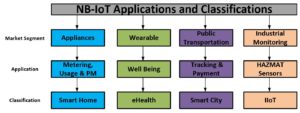
NB-IoT devices will have application platform on UE, so that the user can be communicate with any IoT device.
5G UE and NB-IoT devices will enable many new vertical businesses that do not exist today and will be available in few short years.
ORTENGA has seasoned engineering from Autonomous Automotive, SATCOM, radar, Smart City, WiFi, and Mobile Terrestrial Radio Communications System industries in Antenna, ASIC, Algorithm, HW, FW, and SW engineering disciplines.
V2X Connectivity
Vehicle to other vehicles, gNB, pedestrians, and traffic infrastructure is called V2X connectivity.
In addition to radar for navigation and situational awareness, Autonomous Automotive would require V2X for connectivity.
V2X uses terrestrial mobile communications to connect with other radios in the vicinity and beyond.
Road safety and reaching destination on time require various sensing and coordination between available traffic information and situational awareness.
ORTENGA helps businesses to identify required technical features to realize their business goals and realize the return of investment.
Smart Cities Are System Architectures, Not Mobile Apps
How Integrated Connectivity Between Infrastructure and User Equipment Defines the Next Urban Platform
A Smart City is often described through its applications — restaurant discovery, transit alerts, digital kiosks, mobility platforms.
That framing misses the engineering reality.
As discussed in Mobile Connectivity Is No Longer One Network, seamless experience is never created by an app. It is created by architecture.
When a citizen asks a device for train timing, restaurant availability, or optimal routing, the response is not generated by a mobile application alone. It is the coordinated result of:
- Distributed sensors
- Multi-layer wireless networks
- Edge compute nodes
- Cloud analytics platforms
- Cybersecurity frameworks
- User equipment operating across heterogeneous spectrum
The mobile interface is the endpoint.
The system is the architecture beneath it.
Cities that understand this distinction lead not because they deploy more apps — but because they engineer coherent infrastructure.
Smart City System Architecture Overview

Architecture Stack:
- Urban Infrastructure
- Connectivity Fabric
- Edge Intelligence
- Cloud & Data Platform
- User Equipment Interface
The user device sits at the top of the stack — not at the center of it.
What Actually Constitutes a Smart City Architecture
Smart City maturity is defined by integration discipline, not feature density.
- Deterministic Data Flow
Urban systems produce continuous streams of:
- Traffic density
- Transit location
- Energy load
- Environmental metrics
- Public safety signals
Architecture determines:
- What is processed at the edge
- What is aggregated in the cloud
- What requires millisecond latency
- What can tolerate delay
- What must be encrypted at origin
Without defined data boundaries, scalability collapses.
- Connectivity as a Strategic Asset
Connectivity is not background infrastructure. It is engineered capital.
Dense urban environments demand:
- Spectrum planning
- Antenna optimization in multipath conditions
- Backhaul redundancy
- Network segmentation
- Cyber-resilient design
Connectivity failures are architecture failures.
- Edge Intelligence for Real-Time Decisions
Traffic control, mobility orchestration, and public safety systems cannot tolerate unpredictable latency.
Edge computing:
- Reduces response time
- Reduces backhaul congestion
- Increases system resilience
- Enables real-time AI inference
A Smart City without edge partitioning is structurally fragile.
- Secure Identity and Trust Framework
As transit, payments, mobility, and services converge, identity becomes foundational infrastructure.
Architecture must enforce:
- Device authentication
- Encrypted communications
- Zero-trust network models
- Continuous threat validation
Security cannot be layered afterward. It must be embedded at design.
Architectural Case Studies
Leadership cities treat Smart City as a platform architecture decision — not a procurement exercise.
Barcelona — Platform-Centric Integration
Barcelona prioritized:
- Unified urban data platforms
- Sensor standardization
- Infrastructure-level optimization
- Centralized operational visibility
The emphasis was system coherence.
Munich — Mobility and Industrial Integration
Munich focused on:
- Intelligent mobility systems
- Real-time transit coordination
- Industrial digital integration
- Data-driven sustainability
The emphasis was interoperability and reliability.
Both cities demonstrate the same principle:
Architecture precedes application.
From Vision to Execution: Audit → Design → Validate
Smart Cities do not scale through optimism.
They scale through engineering discipline.
Audit
- Spectrum utilization review
- Network topology assessment
- Sensor placement gaps
- Latency bottlenecks
- Cyber exposure points
- Data silo identification
Audit reveals where integration will fail before deployment.
Design
- Edge vs cloud partitioning
- Latency class definition
- Antenna and RF optimization
- Secure data plane segmentation
- Interoperable standards definition
Design prevents technical debt accumulation.
Validate
- Multi-network stress testing
- Peak load simulation
- Failure recovery modeling
- Cyber penetration testing
- Algorithm validation under real-world constraints
Validation reduces downstream correction cost by orders of magnitude.
Where ORTENGA Operates
ORTENGA works at the layer below the application — where architectural risk lives.
- Antenna strategy in dense urban multipath
- Spectrum allocation discipline
- Edge algorithm validation
- Radar and sensing integration for mobility
- ASIC feasibility modeling
- System-level simulation before deployment
The objective is simple:
Reduce architectural risk before it becomes infrastructure liability.
Smart Cities cannot afford reactive engineering.
They require engineered coherence from infrastructure to user equipment.
Audit → Design → Validate is not optional at urban scale.
It is the only defensible path to scalable intelligence.
Wireless Power Transfer: It’s Not About RF — It’s About Wavelength Discipline
The viability of wireless power transfer is determined long before the first RF simulation is run.
It is determined by commercial constraints.
A scalable product must satisfy real boundaries:
- ~1 W average delivered RF power
- ≤10 W average transmitted power
- Practical transmit aperture (e.g., 10 cm × 10 cm)
- Device-constrained receive antenna geometry
- Deployment ranges aligned with actual use cases
These are not extreme assumptions.
They are disciplined product filters.
Once these constraints are defined, physics narrows the solution space dramatically.
Aperture and Wavelength Together Define the Energy Envelope
In real products, antenna gain is not an abstract number.
Both transmitter and receiver are constrained by physical geometry.
- The transmitter has finite aperture area.
- The receiver is embedded in a device whose size limits its effective antenna area.
For geometry-constrained antennas:
- Larger physical aperture increases energy concentration at range.
- Higher frequency increases gain for the same physical size.
- Beamwidth narrows as wavelength decreases.
- Alignment tolerance shrinks accordingly.
Physical aperture constraints define the achievable power–distance envelope.
Wavelength determines how that envelope is shaped — and how difficult it is to control.
Higher frequency improves spatial concentration.
Lower frequency improves tolerance and robustness.
Wavelength selection is therefore not an RF optimization problem.
It is a geometry-and-control trade.
Three Wavelength Anchors
Assume a 10 cm transmit aperture.
Beamwidth scales approximately with:
HPBW ≈ λ/D
(Exact constants vary with illumination, but λ/D scaling dominates.)

This produces three practical regimes.
~10 GHz (≈ 3 cm) — Broad Energy Zone
- Beamwidth ~15° class
- Alignment tolerant
- Modest tracking requirements
- Significant spatial spillover
This behaves like zone illumination. It supports robust short-to-moderate range delivery, but makes tight spatial containment and multi-device isolation more difficult.
~30 GHz (≈ 1 cm) — Directed Delivery
- Beamwidth ~5°
- Controlled spatial focus
- Moderate steering and tracking requirements
This regime balances energy concentration with manageable control complexity. For constrained apertures and disciplined power budgets, it represents a practical architectural balance.
~100 GHz (≈ 3 mm) — Precision Targeting
- Beamwidth ~1.5°
- High spatial confinement
- Minimal spillover
This enables precise energy delivery and strong device isolation.
But the system now changes character.
Beamwidth Shrinks → Control Complexity Explodes
As beamwidth narrows, wireless power transitions from an RF hardware challenge to a closed-loop control problem.
With narrow beams:
- Small pointing errors cause multi-dB loss
- Device motion interrupts alignment
- Beam scanning must accelerate
- Feedback channels become necessary
- Calibration precision becomes critical
A 15° beam tolerates drift.
A 1.5° beam demands active tracking.
Under realistic commercial constraints — 1 W average delivery, ≤10 W average transmission, practical antenna geometries — the dominant risk shifts from RF component capability to aperture geometry, beam control, and system architecture.
RF hardware is necessary.
Control architecture determines robustness.
Environmental Loss Is Not Uniform Across Wavelength
The discussion above assumes free-space propagation.
In practice, atmospheric absorption varies with frequency:
- Below ~20 GHz, absorption is typically negligible over short indoor ranges.
- Around 60 GHz, oxygen absorption becomes measurable.
- At higher millimeter-wave bands, absorption and rain fade increase.
For short-range indoor scenarios (~10 m), these losses are usually secondary to geometric spreading and alignment.
For outdoor or extended-range deployments, wavelength-dependent absorption becomes part of the architectural decision.
Higher frequency improves spatial confinement — but increases environmental sensitivity.
Again, wavelength discipline matters.
The Real Product Equation
A viable wireless power product must co-design:
- Transmit aperture geometry
- Device receive geometry
- Wavelength class
- Beamwidth
- Tracking tolerance
- Duty-cycle strategy
- Deployment environment
When those variables are aligned, wireless power becomes practical.
When wavelength is selected in isolation, complexity grows faster than performance.
The ORTENGA Perspective
At ORTENGA, product definition begins with constraints:
- Delivered power requirement
- Acceptable transmission ratio
- Physical aperture limits
- Deployment geometry
- Control tolerance
- Environmental assumptions
From those constraints, wavelength is selected deliberately.
Physical geometry defines the power–distance envelope.
Wavelength defines beam behavior.
Beam behavior defines control complexity.
Control complexity defines product viability.
Wireless power succeeds when those layers are co-designed.
It fails when wavelength is treated as an RF afterthought.