- Radar Waveform Design
- Automotive, Short Range Radar (SRR) vs. Long Range Radar (LRR)
- Pulsed Radar Applications in Autonomous Automotive
- MIMO Radars
- Radio Communications and Radar Systems Similarities
- Radar Pulse Compressions Technique and Waveform
- Radar Pulse Compressions
- What are the differences between Lidar vs. Radar Systems?
- Radar Ghosts Target
- Radar equation, how many are there?
- Clutter vs. Noise
- 3D mmW Radar for Automotive
- Mobile Wireless Connectivity for Automotive Application
- V2X Connectivity
Autonomous Automotive is taking shape and will be a reality within the next decade.
There are three main features and/or technology drivers which would enable that new industry, namely; sensors fusion, artificial intelligence, and virtual reality.
Currently most of advanced cars have camera technology to help the driver seeing the vicinity of the car, e.g., during the back up.
LIDAR technology is also being developed so that the car has better visual and sensing of the surroundings.
Short Range Radar and Long Range Radar are also being utilized for awareness capability at least to 500 m regardless visual conditions.
Automotive industry would be relying on all three technologies, “sensors fusion”.
This Forum will be posting related contents and welcome technologist, engineers, scientists for introducing relating materials.
Inquire: info@ortenga.net
Radar Waveform Design
The radar waveform is designed to meet the range, range resolution, velocity, and/or velocity resolution depending on the radar technical requirements.
Autonomous Automotive is particularly interested to detect and identify short and long ranges statics as well as moving objects, whether they are automobile or not.
These put particular importance on the radar waveform design and during system simulations these parameters are optimized to meet desired performance metrics.
Many other system RF impairments play role in the waveform design.
Partner with ORTENGA to design and develop Autonomous Automobile radar waveform.
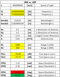
Automotive, Short Range Radar (SRR) vs. Long Range Radar (LRR)
Physics tell us that lower frequency has longer radio range whereas higher frequency provides shorter radio range via free space loss.
Also, Physics tell higher frequency, shorter wavelength provides better spatial resolution than longer wavelength, lower frequency.
Automotive market tells us that SRR and LRR are required for a successful product. Many automotive radar products have missed this product concept and cannot successfully capitalize on ROI.
The following table illustrates SRR vs. LRR.
If you ask these companies why haven’t design your product for both SRR and LRR, the typical response is cost concern.
The cost drove their product concept, even though there is not much market for short range or long range by itself.
This shows two fundamental conceptual product definition issue:
- The cost drove the definition of the product, instead of looking for a cost-effective solution which has successful ROI
- The definition product did not look for alternative architecture which can mitigate the cost
Work with ORTENGA to define your product.
Pulsed Radar Applications in Autonomous Automotive
“Pulsed Radar Applications in Consumer Electronics” webinar sponsored by ORTENGA was presented on June 24, 2020.
This webinar covers architecture and function of Pulsed Radar as well as delving into some its applications for Consumer Electronics.
MIMO Radars
MIMO aka Spatial Multiplexing is being used in 5G as well as WiFi technologies.
New Radars also utilize MIMO waveforms to optimize for position and velocity accuracy/resolution, simultaneously.
MIMO Radar also allows combination of Active and Passive illuminators, which can enhance the above resolutions.
MIMO relies and exploits multipath scatters and combines the received signals in a such way to optimize for SINR.
In radio communications application, there are handful of transmitted coding which are optimized per channel and predefined. When SRS is transmitted, the receiver replies back a number which reveals the best signal coding received for that channel. Then, the transmitter starts transmitting data with the same coding until the channel conditions are changed.
Similar algorithm can be utilized in the MIMO Pulsed Radar to enhance SINR.
Partner with ORTENGA in design and development of MIMO Radar.
Radio Communications and Radar Systems Similarities
Radio Communications and Radar have been two distinct technologies in their own industries. However, in the past decade, the advancement of technologies both in Academia as well as implementations and integrations of radio and processor in to more devices from handheld to terminal based have led to some interesting overlaps between these two industries. This blog will briefly walk through the similarities and overlap of implementations.
Perhaps the most difficult problem of Terrestrial radio communications is fading mitigation. Fading is not only function of frequency but also of the environment or terrain. This makes it new problem to solve, every time, the radio is supposed to operate at different frequency or environment.
Radars typically operate in open environments and the small echo from their targets arrives at receiver directly. Any multipath echo is too small in amplitude to be resolved with meaningful information. On the other hand, the radar target aspects impact the radio signal similar to what environment do to radio communication signal. Target scintillation is well known issue to radar industries. Radar target scintillation can easily vary the amplitude of echo signal as much as 10dB for milli-radian variation of target aspect. Target scintillation is also function of frequency and target aspects.
Radar Cross Section, RCS, subject matter experts spend their life time to model various target at different frequencies to model radar echo signal behavior to design appropriate radar.
Multipath Fading in Terrestrial Communications and Target Scintillation of Radar Cross Section, RCS, requires appropriate waveform design. In Communications, the waveform depends on environment modulating this waveform and how to retrieve or reconstruct the waveform at the receiver. To optimize the waveform for maximum SINR, the waveform is carefully designed for its timing metrics.
In radar, the waveform depends on target modulating this waveform and how to retrieve desired information about the target. Target “finger print” is on the echo waveform. To optimize the waveform for maximum SINR, the waveform is carefully designed for its timing metrics.
MIMO technology utilized orthogonal waveforms from multiple transmit antennas, independent waveform, to arrives at the receivers and be combined in such a way that SINR is fairly constants for all receivers.
In case of MIMO radar, each orthogonal waveform is designed to one desired metrics of target and the received signals can be processed to retrieve the desired metric.
There are typically 4 models that are used to simulate the behavior of target RCS, Swerling 1, 2, 3, & 4.
Swerling models 1& 2 are based on independent and identical distribution, iid, scatters of target aspect, which is effectively similar to Rayleigh fading model. Swerling model 1 and 2 are slow and fast RCS variations with respect to dwelling time, i.e. slow and fast fading with respect to symbol time in radio communications.
Swerling models 3 & 4 are based on specular RCS aspect, similar to Rician fading with dominant path.
Swerling models 3 and 4 are slow and fast RCS variations with respect to dwelling time, i.e. slow and fast fading with respect to symbol time in radio communications.
It may be surprise to some as how similar the radar and terrestrial radio communications are, yet it worth to note it is behavior of radio waves in environment whether it is used for communications or radar.
ORTENGA is a consulting firm with Subject Matter Expertise in both Radio Communications and Automotive Radar applications.
ORTENGA designs and develops Radio Communication or Radar Waveform.
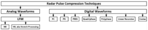
Radar Pulse Compressions Technique and Waveform
It is well known that radar waveform can either be tailored for range or its resolution. In other words, the requirements for long range and fine range resolution are contradictory in nature. In addition, it is also true that range vs. velocity resolution have contradictory design constraints which cannot be met simultaneously, unless more sophisticated waveforms are utilized which are known as Pulse Compression Technique.
The following diagram illustrates various Analog and Digital Pulse Compression Waveforms which are utilized by Radar Waveform designers to optimize range and its resolutions.
Pulse Compression and MIMO radar can be utilized to design appropriate waveform constraints for range, range resolution, and velocity resolution.
Radar Pulse Compressions
As Radar technology becomes part of automotive and commercial drones, new requirements are developed to provide for this new market appropriately. Some of the technical challenges to be addressed are stringent range and radial velocity resolution for moving target as well as radar itself. It is well known that range resolution requires lower PRF, while radial velocity resolution requires higher PRF. Obviously both requirements cannot be met, simultaneously. Pulse compression technique is used to mitigate this issue. PN pulses can be used in a way that can produce optimum resolution for both range and radial velocity. Barker code of various lengths provides an example of PN pulses.
What are the differences between Lidar vs. Radar Systems?
Radar is an acronym for “Radio Detection and Ranging”.
Radar illuminates a target via radio waves and listens to the echo for acquiring information about the target.
Nowadays, radar is much more advanced technology and also detects the target radial speed, direction of arrival, type, and its size.
Originally, radar’s technology was intended for military applications and over time it has find its way to commercial applications.
Recently, radar’s technology is being designed and developed for autonomous car, train, and plane industries.
Radar’s range could be as short as 100 m up to 250 Km.
Lidar stands for “Light Detection and Ranging”.
Lidar uses Laser/Light instead of radio waves and can depict good resolution picture of the target.
Lidar are for much shorter range of the target, 100 – 150 m.
Nowadays, both Radar and Lidar use sophisticated digital signal processing techniques and algorithms to acquire significant information about the target of interest.
Radar Ghosts Target
In radar processing, ghost target appears when there is a multipath of echo signal reaching receiver. This causes the receiver having difficulty in differentiating, identifying, and tracking the actual target.
Automotive radar experiences moving target as well as the radar equipment, which further exacerbates this ghost target vision situation and requires appropriate radar signal and data processing, in addition to front end HW.
The echo signal typically could have either Rician or Rayleigh profile for small scale fading.
In order to mitigate ghost target vision, there are 2 parameters that have to be carefully analyzed and designed, namely; signal BW and symbol rate. These parameters are the knobs to avoid signal dispersion and time variant channel, respectively. Obviously, understanding the multipath fading manifestation is fundamental in solving problems at hand.
Radar equation, how many are there?
Radar equation relates transmit and received antenna gain, power, radar cross section, operating wavelength/frequency, range, and noise. Consequently, radar signal to noise ratio can be computed. There are 3 classes of radar; Search, Track, and Weather, each with its own radar equation which are used to relate physical design parameters to performance metric of a given radar.
Radar engineers use appropriate equation for designing and modeling given radar. Search radar is utilized to scan given sky volume to find target, an obvious example is airport radar. Tracking radar is utilized to lock onto a target and track its movement. Whereas, Weather radar is utilized to analyze precipitations and movement of rain, snow, and/or storm.
Some important observations regarding radar equations are that Track and Weather radar equations have squared wavelength dependency, whereas Search radar does not, directly. On the other hand, Track and Search radar equations have inverse quadratic range dependency, whereas Weather radar has only inverse squared range dependency.
Clutter vs. Noise
Clutter is legacy radar terminology for background noise of target under surveillance, TUS. Radar engineers make clear distinction between noises vs. clutter. Noise is an unwanted signal that typically generated inherently by electronic systems, such as receiver. Typical radio impairments are due thermal, phase error/time jitter, and quantization which are associated with noise.
Clutter on the other hand is the unwanted signal picked up by the antenna or antenna array in the radar system. Typically, radiation pattern of antenna consists of main lobe, side lobes, and back lobe. The main lobe is wanted whereas side lobes and back lobe are unwanted radiations. During signal reception, the side lobes and back lobe are also picking up signal, which is not from the target under surveillance. Since the side lobes and back lobe are much lower level below the main lobe, the unwanted signal contributions due by them are also weaker within the receiver, nevertheless the clutter exist and needs to be quantified. Therefore, radar systems engineers include clutter in the link budget of radar receiver.
3D mmW Radar for Automotive
Radio Detection and Ranging, aka radar, has been used since WWII in military applications, then in Avionic, and recently entered into Automobile applications. Automotive radar equipment are typically used for Collision Avoidance, however as Autonomous Car is becoming reality within few short years via advancement of wireless mobile communications, 5G, and connected cities, IoT, 3D mmW Radar will find its way into next generations of cars.
Originally, radar was meant to detect and provide the distance/range to the target. Then, it evolved to provide the speed of the target using Doppler frequency shift of the Electromagnetic, EM, echo signal. It further enhanced to estimate Time of Arrival, ToA, then Direction of Arrival, DoA, using pulsed waveform and measuring the round trip time of the echo signal. The EM echo is created by reflection from the target. Target effective area seen by radar is called, Radar Cross Section, RCS. Each target has its own radar signature/RCS and can be cataloged and used for identification with advance digital signal processing of the EM echo signal, aka radar signature. Radars are characterized either by CW or Pulsed modulation. CW radar is better for frequency resolution of the echo, which translate to speed of the target, whereas Pulsed radar is better suited for time resolution of the echo, which translate to ToA. 3D mmW radar will provide 3 dimensional field of view of the car.
There have been handfuls of companies that make radar units for car manufacturers. Now that the market is growing exponentially and the car radar is more than feature on high end cars, automobile manufacturers have started investing internally on radar technology design and development.
To learn more about the automotive radar technology and its market, inquire at info@ortenga.net.
Mobile Wireless Connectivity for Automotive Application
Automotive Connectivity will be growing within the next few years in high end and luxury Automobiles and matures as must have feature by 2030.
There are two platforms which will provide the wireless connectivity, LEO SATCOM and 5G Terrestrial networks.
Size, Weight, and Power consumption, Temperature tolerance, SWaPT, will be making or breaking thresholds for any LEO User Terminal market acceptance by automotive manufacturers. Later on, Cost will join the C-SWaPT as another metric for the industry.
The 16×16 antenna array will be ~30cm x 30cm, ~5cm thick including ASM, FEM, TRx, MODEM, and APQ for Ku band. Therefore, it will fit in any automobile.
The power consumption can be tailored for automobile applications supplies with range of ~1 – 20 W depending on Rx, Tx, or sleep modes. Average transmit mode power consumption is ~15W.
Temperature tolerance will be handled with meticulous Thermo-Safe design.
Regarding 5G mmW band, this design will be housed in even smaller volume of ~10cm x 10cm x ~3cm including all electronics necessary for Mobile User Equipment and power consumption ~10W.
It is worth mentioning that a combined LEO UT and 5G UE can be designed within ~40cm x 40cm to operate in both LEO and Terrestrial networks. The unit cost of such a terminal can be approximated to ~$5000.
Augment ORTENGA in your design and development team to tailor LEO UT and/or 5G UE/CPE/gNB/FWA product.
V2X Connectivity
Vehicle to other vehicles, gNB, pedestrians, and traffic infrastructure is called V2X connectivity.
In addition to radar for navigation and situational awareness, Autonomous Automotive would require V2X for connectivity.
V2X uses terrestrial mobile communications to connect with other radios in the vicinity and beyond.
Road safety and reaching destination on time require various sensing and coordination between available traffic information and situational awareness.
ORTENGA helps businesses to identify required technical features to realize their business goals and realize the return of investment.