- Envelope Tracking Algorithm
- The case for using X55 for LEO SATCOM Applications
- SLL Management Algorithm
- Beam Tracking Algorithm
- What is Beam Splitting?
- iPhone 12 Semiconductor Outlook
- Beamforming Algorithm
- Wireless Communication System and Radar Design Misconceptions
- What part of radio needs calibration?
- Radar and/or Wireless Systems Essentials
- IR-UWB Transmitter Architecture
- Design vs. Gate Reviews
- Impact of Aperture Jitter, aka Aperture Uncertainty, on Sampled Signals
- Interleaving Converters gNB, ICgNB, Architecture
- The Jobs which will be replaced by Robots?
- What are DPD challenges for UWB signals?
- Why should you use FPGA for your prototype?
- 5G Infrastructure Design Flow
- Why should you use DOE in your System Design?
- What is application of Perturbation Theory in 5G?
- NB-IoT Applications and Classifications
- Why do you need Systems Engineering in your team?
- Why should you be using MIMO Radar?
- Why Pioneer Engineers Develop their own Tools instead of using CAD?
- COTS Prototype Pros vs. Cons
- Apple 5G MODEM SoC
- Operating Systems Classifications and Applications
- Product Conceptualization and Realization
- What is an Edge Device?
- What are the differences between HW Prototype and Reference Design?
- Margin vs. CE Product Delivery to Market
- Glucose Detection and Measurement
- OneWeb LEO UT Prototype Architecture
- Amazon LEO SATCOM Payload Architecture
- The Art of Triangulation Location Finding
- Debugging and Design of Experiment, DOE
- Does an amplifier help improving the signal to noise ratio?
- 5G Health Concern
- What is an Algorithm?
- 802.11ay, Next Generation WiGig Packet Format
- Top Skills for Project Ownership and Leadership
- Why On-Board Processing Satellite Payload will be enabling LEO?
- Regenerative LEO Satellite Payload Architecture
- LEO SATCOM Beam Sequencing Requirements
- LEO UT and 5G gNB Beamforming Options
- SATCOM Coding
- 5G Concatenated Coding Architecture
- Wearable Technology
- What are Radio Link and Line-up Budgets?
- Which Waveform should be utilized for LEO SATCOM, DVB-S2, 3GPP, or CDMA Waveform?
- What is the importance of G/T?
- LEO Down Link Throughput
- Successful Electronic Consumer Product
- The impact of Antenna Efficiency on Antenna Temperature
- 5G Phone ODM Players
- LEO SATCOM Architecture of Choice
- Who are LEO SATCOM Players?
- Why DSP Algorithms are implemented via Fixed Point in FPGA?
- Wireless Communication Systems Decomposition Flow
- Automotive Hidden Antenna
- What is Interleaving and Why it is used?
- Rayleigh vs. Rician Fading
- WiGig 802.11ad Data Rate vs. Range
- WiGig, 802.11ad Packet Format
- MIMO OFDM Systems Architecture
- Water Fall Curves for BPSK, QPSK, 16, 64, 256, 1024, and 4096 QAM
- Which should be used, SNR or Eb/N0?
- 802.11ad EIRP and Transmit Power
- 5G Infrastructure and 802.11ad Access Point Opportunities for Holographic Beamforming, HGBF, mmW Architecture
- Open Source Interconnections, OSI, Layers
- 4G vs. 5G Waveform Characteristics
- Fading Manifestations and Mitigation Techniques
- Antenna Tuners
- 5G Use Cases Decomposed to Communications Platform
- 5G Beamforming Architectures
- 5G Beam Forming Options, Diodes, LCD, MEMS Comparison
- Plan for Success
- What are the Criteria for Startups to be acquired by a Bigger Company?
- Product Over and/or Under Specifications
- LEO Down Link Throughput
Envelope Tracking Algorithm
Envelope Tracking, ET, Algorithm have mitigated Power Added Efficiency, PAE, of Power Amplifiers, PA, in UE as well as eNB infrastructure during that past decade.
It is well known that maximum PAE is reached when PA is near compression point. However, operating PA at or near compression point produces signal distortions due to non-linearity behavior of PA which effectively reduces EVM of transmitting signal, system KPI.
In order to mitigate the signal distortion, the PA nonlinearity can be simulated or characterized. Then the desired signal can be distorted intentionally prior feeding the PA in such a way that after the PA amplification, the desired signal becomes linear again. This algorithm is called Digital Pre Distortion, DPD, and widely used in UE, eNB, and gNB infrastructures.
Partner with ORTENGA to design and develop DPD and ET algorithms for your new product.
Inquiry send to: info@ortenga.net
Posted on December 31, 2019
The case for using X55 for LEO SATCOM Applications
Qualcomm X55 System on Chip, SoC, is 5G broadband MODEM, i.e. 800MHz signal BW, which not only supports Sub 6 GHz but also mmW bands at 28 and 29 GHz spectrum.
Although, Qualcomm RFIC transceiver does not support LEO SATCOM interface, the X55 SoC MODEM can.
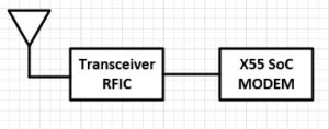
Here are some of advantages of using X55 SoC MODEM for LEO UT applications. The 3GPP MODEM has beamforming, beam tracking, multiple antennas for beam splitting capabilities which can also be used to support LEO SATCOM. In fact, the MODEM can support both 5G and LEO networks, depending on the network signal availability and quality. The MODEM is scalable to accommodate various Waveforms timing requirements. It also has excellent sensitivity, spectral efficiency at low Eb/N0, power efficiency [bps/J], etc. The coding rate is scalable to Eb/N0. The MODEM supports radio front end calibrations.
Partner with ORTENGA to design and develop 3GPP and/or LEO SATCOM product.
Inquiry send to: info@ortenga.net
Posted on December 30, 2019
SLL Management Algorithm
Side Lobe Level, SLL, management is requirement for any beamforming and beam tracking radio communications or radar systems. gNB , LEO SATCOM, 802.11ad/ay, and radar systems rely on beamforming and beam tracking technologies as well as SLL management algorithm to comply with FCC unwanted emission requirements which are really needed for multiple access or users’ radio coexistence.
SLL management algorithm works hand in hand with beamforming and beam tracking algorithms. As the beam formed and tracks the targets, the radiation pattern is dynamically changing every fraction of second, e.g. every couple of hundred microseconds in LEO SATCOM, therefore the SLL must be managed automatically to meet FCC requirements at all times to avoid interfering with other users. This is only possible if SLL management algorithm is in place within the radio system to ensure not exceeding an upper level SLL, hence safe level for other users or misidentify the target in radar applications.
Partner with ORTENGA to design and develop SLL management algorithm for your product.
Inquiry send to: info@ortenga.net
Posted on December 27, 2019
Beam Tracking Algorithm
5G and SATCOM not only rely on Beamforming but also on Beam Tracking algorithm.
Beam tracking is needed when transmitter, receiver, or both are mobile, and required in addition to Beam forming algorithm.
Beam tracking algorithm can be categorized into 3 different use cases, namely; gNB, GEO and LEO SATCOM applications.
- Beam tracks mobile targets, while the transmitter is stationary. For instance, gNB tracks mobile UE.
- Beam tracks stationary target, while the transmitter is mobile. For instance, mobile SATCOM UT is tracking GEO satellite.
- Beam tracks mobile targets, while the transmitter is mobile. For instance, mobile SATCOM UT is tracking LEO satellites.
All of the above algorithms can be realized for new technologies.
ORTENGA can design and develop the above algorithms depending on the applications and use cases.
Inquiry send to: info@ortenga.net
Posted on December 24, 2019
What is Beam Splitting?
Beamforming, BF, is an electronic technique to form Electromagnetic waves in the desired direction either for Transmit or Reception of radio waves. BF can be designed with either Phased Array Antennas or Holographic Metamaterial Antennas.
In gNB or LEO applications, there are use cases which either multiple users or multiple satellites have to be illuminated. In those scenarios, the Phased Array Antennas or HGBF antennas can split the beam in two or even multiple directions with the expense of losing antenna array gain or increased HPBW.
Since the beam splitting occurs electronically, therefore depending on the electronics of the radio front end, this can occur in fraction of seconds and appears seamless connectivity.
In fact, gNB infrastructure currently is using this technique for 28 and 39 GHz mmW 5G technology.
The Beam Splitting technique can also be utilized in LEO SATCOM application.
Partner with ORTENGA to design and develop your BF product.
Inquiry send to: info@ortenga.net
Posted on November 25, 2019
iPhone 12 Semiconductor Outlook
iPhone12 is expected to be announced by September 2020 and supports 5G in addition to legacy 4G and 3G. The following top level top diagram illustrates iPhone 12 major components by various semiconductor companies in addition to Apple application processor, power management IC, and WiFi/BT IC. Also the diagram predicts the semiconductor technology which will be utilized for realizing these major ASICs.

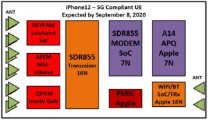
Needless to say that many antennas will be designed to support iPhone 12. For instance, there will be 4 mmW Antennas to support 5G applications.
Partner with ORTENGA for market and competitor analysis.
Inquiry send to: info@ortenga.net
Posted on November 22, 2019
Beamforming Algorithm
5G and Autonomous Automotive LIDAR and Radar rely on Beamforming Technology.
Beamforming, BF, is based on Antenna/Sensor Array, where collectively work together to form the beam in transmit or receive sensing.
The inputs to the algorithm are frequency, number of elements in the array, inter-element spacing in the array, polarization, pointing direction of the beam, required SLL.
The outputs of the algorithm are inter-element phase shift, antenna element voltage/current excitations for open loop implementation.
For closed loop implementation, the algorithm also utilizes the sensors in the array and/or feedback from receiver to make additional corrections due to impairments or tolerance of electronics in the system.
Partner with ORTENGA to design, develop, and implement BF algorithm in FPGA for your project.
Inquiry send to: info@ortenga.net
Posted on November 13, 2019
Wireless Communication System and Radar Design Misconceptions
There are 4 major blocks in any Wireless Communication System or Radar applications which impact the key metric performances, namely; Antenna, Transceiver, Mixed Signal Converters, and MODEM.
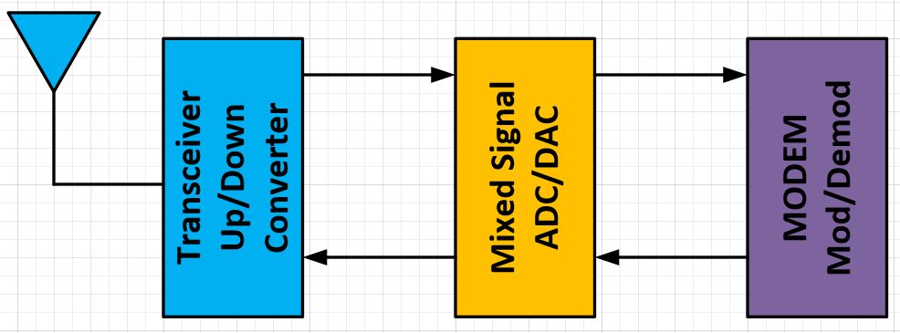
Antenna solely operates in radio frequencies. Transceiver operates in both radio and intermediate frequencies. Mixed Signal blocks either convert analog to digital or vice versa. MODEM solely operates in digital domain.
On the surface, it may appear that each major block is independent of other blocks or there is only dependency between adjacent blocks, e.g. Antenna and Transceiver. In a reality, all of these blocks are interdependent and designed precisely to interact with each other in tailored and optimized manner.
For instance, a MODEM can control and optimize antenna performances when the antenna switch from one frequency band to another or when Transceiver temperature changes over time.
An optimized radio or radar systems design take into account many interaction issues between each block and defines their performances that not only ensures their functionality but also operate with desired specifications as the environmental conditions around them changes. For instance, when you are using your mobile handset, depending how you hold the handset the antenna surrounding changes, therefore its input impedance changes, which in turn changes the efficiency of the antenna, if it is not properly retuned via MODEM.
It is also worth noting that there is no unique line up or unique requirements that works for 5G or IoT applications, each design would have its pros and cons, depending on which market and use cases are being targeted.
If you are designing any of the above blocks for 5G, IoT, or Radar markets, you should have radio systems engineers whom look into all of the interaction issues and validate any assumptions before requirements are locked in for designers.
In fact, SW and FW also have direct impact on HW and vice versa. Algorithms that control the radio front end and process the incoming and outgoing digital signals are implemented either in SW or FW within DSP core in the baseband unit or FPGA.
Consult with ORTENGA for your products’ requirements that may go into either Wireless Communication System or Radar system applications. ORTENGA provides you with analysis and computations to validate use cases target specifications and design goals.
Inquiry send to: info@ortenga.net
Posted on November 9, 2019
What part of radio needs calibration?
In general, anything in the radio that changes or varies with Process (i.e. part to part), Voltage, Temperature, aka PVT, and frequency has to be calibrated with some algorithm.
Part to part, aka Process variations are static in nature. In other words, the behavior of the devices can be characterized before using the electronic devices and appropriate algorithm implemented to account with process variations.
Voltage, Temperature, and Frequency variations are dynamic in nature. In other words, the device can start at given voltage, temperature, or frequency and changes occur during the operation of the device which causes these variations. The algorithms to compensate for these variations should occur dynamically based on the information or feedback from the device.
Typically, analog components have tolerances as well as variations over PVT which requires calibration to guarantee required performance during electronic devices operation.
Antenna array phase alignment could be one of these metrics which has to be calibrated before successful beamforming with expected performance of beamforming during operation.
Partner with ORTENGA to design and develop the appropriate calibration algorithm and its implementation for your new product.
Inquiry send to: info@ortenga.net
Posted on October 9, 2019
Radar and/or Wireless Systems Essentials
Any radar and wireless systems is comprised of three core subsystems which impact the overall performances and/or limitations of the system, namely; Radio Systems Architecture, Digital Communication Systems, and Digital Signal Processing, DSP.
The following diagram illustrates any radar and wireless systems essentials.

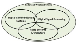
Systems Architecture subsystems deal with air interface aspect where radio waves are propagating. The radio’s function is ensuring the signal integrity of the radio frequency signals and maintain adequate signal to noise ratio while playing well with other users for that spectrum.
The communication systems is designing appropriate waveforms as well as coding and assigning required Eb/N0 in such a way that meets the channel conditions. This is theoretical aspect of the overall systems.
Both Radio Systems Architecture and Digital Communication Systems define the upper and lower limits for that system. Once an architecture and waveform is chosen, the system is bounded/constraint and can be designed. In order to implement the design into actual HW/FW/SW, DSP is needed.
DSP function is to process the transmitting and receiving signals in such a way that meets radio as well as digital communication systems requirements. DSP is where various algorithms reside which not only address the radio impairments and mitigations but also deal with generating and retrieving the data based on the requirements by radio as well as waveform.
DSP algorithms are typically implemented in FPGA to save cost of design and development, time to prototype and customer demonstrations.
Large and established organizations typically have engineering resources for these three distinct areas to support any wireless or radar system. There are times however, either because of multiple projects or other limitations in engineering resources there is skills gap in one or more areas. ORTENGA is prepared with SME to provide services to close that skill gap for duration of the project.
Here are some typical pitfalls that any organization with limited resources may fall into. They plan and rely on semiconductor vendors to provide actual system design which fits and meets specifications of new product. The fallacy is that, although ASIC devices may provide functionality for their system, yet it could never meet all specifications for actual use cases, once the HW/FW/SW are locked in and designed without thoroughly been vetted by system engineering. Too often, the prototype meets customer expectations, but the product is not manufacturable.
In order to design any system, radar or wireless communication, analysis and trade-offs between the resources and interfaces in the system are made to determine the upper and lower bounds of performance metrics.
Whether you already chosen ASIC for your new product or plan to down select them, it is imperative to have system engineering to review and make/adjust recommendations based on the use cases.
Partner with ORTENGA to acquire valuable inputs and/or feedback regarding proper system engineering of your new product.
Inquiry send to: info@ortenga.net
Posted on September 21, 2019
IR-UWB Transmitter Architecture
In recent times, Impulse Radio – ultrawideband (IR-UWB) system has been considered as a promising technology for short-range wireless applications due to its various inherent properties, such as low power consumption, low cost, pulse communication like radar, high data rate, etc. In 2002, the Federal Communication Commission (FCC) authorizes the use of UWB technology for the commercial product under unlicensed spectrum. Afterward, IR-UWB technology drawing the attention of technologist, entrepreneurs, researchers around the globe for wide-range of promising applications such as indoor positioning and tracking, vital sign detection, ultra-fine infant movement detection, real-time monitoring of highway, bridges and other civil infrastructure, etc.
The key component of the IR-UWB system is the generation of IR-UWB pulse, which should be very short in time and higher in amplitude, ideally a delta function. However, the average power of generated pulse should not exceed 75 nW in 1 MHz resolution bandwidth (equivalent to EIRP of –41.3 dBm/1MHz). The average EIRP level for a higher voltage amplitude pulses can be met by lowering the PRF value. In order to limit the interference with other coexisting narrowband wireless system, FCC limit the peak power up to 1 mW in 50 MHz resolution bandwidth (equivalent to EIRP of 0 dBm/50 MHz). The generated pulse should come under the specified limit. The higher amplitude of generated IR-UWB pulse helps to increase the positioning range (or radar range), though, the shorter time width of IR-UWB pulse help to resolve the multipath.
There are several commercially available UWB system provided by Decawave, Time Domain, Ubisense, Zebra Technology, etc. These products can generate a short time UWB pulse, however, a major restriction associated with the existing IR-UWB systems is the limited output peak power. The limited peak output power restricts the range of indoor positioning and degrades the signal to noise ratio (SNR) for radar system application. The system performance becomes even worse for the non‑line‑of‑sight (NLOS) condition. In some cases, the transmitter must assemble into the concrete wall or hide into the wooden blocks. Therefore, it is important to generate the IR-UWB pulse with higher peak output power. The power consumption should be as low as possible (below or at the minimum horizon of reported values) for robust system application. There are mainly four techniques or architecture, which is being used for IR-UWB pulse generation.
Spectrum Filtering: The spectrum filtering approach is to generate a delta function voltage pulse and filter it out into regulated spectrum. The generated IR-UWB pulses are limited to monocycle, operating under 2GHz band. The FCC spectrum mask limit and inefficiency of transmitter antenna at lower frequency band are major concerns with monocycle pulse.
Up-Conversion: The up-conversion method first generates a baseband signal and up-converts into the desired band of frequency using a mixer and local oscillator (LO). The generated pulse will be multi-cycle having reasonably good output peak power, but the power consumption is very high due to use of mixer and LO in the circuit.
Digital Edge Combining: This method utilizes the rising and falling edge of the digital pulses. The relatively delayed digital pulses are combined and pass through smoothing filter to get a multicycle IR-UWB pulse. The output peak power is very low due to the use of digital blocks. Hence, not useful for ranging and radar application. However, the transmitter architecture is desirable for short distance high data rate communication.
Distributed Pulse Synthesizer: This method uses an impulse voltage as an input to a distributed pulse synthesizer and performs the signal scaling, signal inversion, time-shifting on an impulse voltage signal. The signal addition is performed at the output terminal of the pulse synthesizer to produce the desired multi-cycle IR-UWB pulse. Among all the techniques, the distributed waveform synthesizer has potential to generates multi-cycle high voltage IR-UWB pulse with ultra-low power consumption.
The distributed pulse synthesizer architecture is the most efficient architecture among all, which is capable for the generation of significantly higher peak output power with reasonable pulse width. However, the output peak power generation is now limited by the fabrication technology, where the transistor breakdown for higher output voltage swings. Some of the IR-UWB transmitters fabricated using GaAs HBT is reported having significantly larger output peak power. The GaN technology will have higher breakdown voltage so that could be also useful to generate higher peak output power.
Apart from technology enhancement, the alternative way to improve the output peak power of the transmitter is spatial beamforming, where multiple synchronized transmitting nodes transmit pulses and superimpose in the space to increase the radiated power. The beamforming will not only facilitate significantly higher output power but also improves the radiation efficiency. It emanates with the radiated beam in optimized direction, which will be beneficial for IR-UWB radar and imaging applications.
In conclusion, the architecture of IR-UWB pulse generator is now limited by the fabrication technology (breakdown voltage of transistor). Even if we improve the fabrication process for higher breakdown voltage, the designed circuit can’t be fabricated on single-chip since the other digital blocks are designed for silicon fabrication technology. The alternative way is beamforming, which does not only help to get higher output peak power but also come with steerable beam. The steerable beam will add an advantage on IR-UWB radar and imaging application as well as peer-to-peer ranging for longer distance.
Author: Arif Hussain
Inquiry send to: info@ortenga.net
Posted on September 14, 2019
Design vs. Gate Reviews
Any successful engineering project goes through many reviews before completion and delivery of project launch. The reviews can be categorized into distinct Design vs. Gate Reviews.
Design reviews are peer reviews in non-threatening atmosphere among engineers who collectively are responsible to execute and deliver the project. The atmosphere of review is set to convey that the engineering team bears the responsibility for success of the project, not just presenter. The highest ranking engineering member will be perhaps one director who owns the engineering team. There is no V.P. Engineering in the design reviews meeting. The chair of the design review meeting set the tone for collective participation in an atmosphere where engineers can interact with feeling of mutual respect. The chair documents and collects a list of accomplishments as well as gaps that are observed. Collectively engineering rates each item in the gap list for its risk to the project outcome and prioritize.
Gate reviews are taken place after many design reviews are completed successfully with all action items completed before meeting with the executives and project stakeholders. The objective of gate review is not to list what is working; it is more importantly to highlight issues, what may not be working, that may cause issue down the line. The participant in the Gate reviews are directors and above, no engineering individual contributors is in the meeting. Gate reviewers should be keen to scratch beyond the surface to find issues hidden. A typical gate reviews is just like Launch review by NASA, many of us seen on Apollo movie. The mission control is asking each engineering team lead only, the status of their section, and if it is a GO, the mission control moves to the next team. On the other hand, if it is NO GO, the mission asks further questions to clarify and understand the extend of the issue and have to decide whether to proceed to stop the launch.
Mixing these two, Design and Gate reviews, never achieves anything useful.
Inquiry send to: info@ortenga.net
Posted on September 7, 2019
Impact of Aperture Jitter, aka Aperture Uncertainty, on Sampled Signals
Ultra-Wide Band, UWB, signals are part of 5G, MIMO Radar, and 802.11ad/ay Applications.
According to Nyquist sampling theorem, the uniform sampling frequency shall be at least equal or faster than twice the signal of interest bandwidth. This theorem holds while the sampling occurs near DC. If the actual signals to be sampled are at IF or RF frequencies, additional precaution shall be taken into account to ensure the fidelity of signals.
Aperture Jitter, aka Aperture uncertainty, is the uncertainty in sample to sample variations in encoding process. Aperture uncertainty yield three unwanted signature, reduces SNR, increases phase error, and/or increases Inter Symbol Interference, ISI.
New architectures are based on IF and even RF sampling using interleaving or fast sampled ADC and DAC for receiver and transmitter, respectively.
The architecture design and systems requirements are keys to success of your product.
Partner with ORTENGA in design and development of your new communication systems or radar.
Inquiry send to: info@ortenga.net
Posted on August 30, 2019
Interleaving Converters gNB, ICgNB, Architecture
5G Infrastructure, aka gNB, architecture and design faces many challenges to meet Size, Weight, and Power, SWaP.
Legacy design gNB architecture relies on HBF architecture, whereas more advanced design and risk taking entrepreneur startups utilizes HGBF architecture. Both of these architectures require significant number of transceivers which not only add to the unit cost, CAPEX, but also have to be characterized, calibrated, and compensate RF impairments before and during operations, OPEX.
Keep in mind, the prime value proposition and motivation going from 4G to 5G is to reduce OPEX, $/bps/Hz. Any active electronics generates heat which requires cooling regulations to maintain performance and reliability over its life span.
Removing Transceivers can save energy, cooling, characterization, and RF impairments’ compensations cost, in addition to NRE for design and development and time to market.
Interleaving Converters gNB, ICgNB, architecture with proper filtering can eliminate the need for transceivers.
Partner with ORTENGA in design and development of your new Radio Architecture and Communication System and radar Design.
Inquiry send to: info@ortenga.net
Posted on August 28, 2019
The Jobs which will be replaced by Robots?
With the advance of technology in robotic, machine learning, and artificial intelligence, many have predicted that some jobs will be fulfilled with robots instead of human.
Let’s look back to predict what will happen in few short years.
In semiconductor industry, the fab environment and its requirements are extremely stringent. A high volume semiconductor fab is 10000x or more cleaner, less particles in air per cubic foot, than the best medical surgery room in the world. Historically human with bunny suite operated semiconductor fab machines, but nowadays, it is robots which operate machines.
Also, pick and place robots have been utilized to fabricate PCB HW for high volumes product facilities.
Here are some keywords that you should be aware for the kind of jobs which will be replaced with Robots.
-24/7 Global Support – that seems to be a goner, as soon as robot can take over – no human can work around the clock, even if s/he did, they get sick, go vacation, etc., what does the organization have to do?
Monitor and Control – this requires awareness of certain events, and implicitly requires around the clock monitoring and under circumstances adjust a stimulus to control the outcome. This would be an ideal job for IIoT with sensors to monitor, and computational algorithm to control.
Place and Route – Digital Semiconductor components and interconnections are fairly automated, but it could become completely without human interactions. RF components and interconnections are still being manually placed and routed by engineers, which could be next for simplifications and perhaps some automation. The same methodology could be applied to PCB design, which is time consuming and shortage of designer, could be automated to a level, which Design Rules Check, DRC, could catch any potential issue.
Collaborate with ORTENGA for special radio project, we provide services for duration of the project and validate your design for successful transition to production.
Inquiry send to: info@ortenga.net
Posted on August 26, 2019
What are DPD challenges for UWB signals?
Digital Pre Distortion, DPD, technique is widely used in mobile UE to linearize Power Amplifier, PA, output signal, such that it can be run into saturation mode without violating spurious and unwanted emissions while mitigating transmitter power efficiency, hence increasing the battery life time.
It turns out that spectral efficiency and power efficiency have contradictory constraints.
As we pack more bits into one symbol or alphabet, higher QAM, then the signal becomes more spectral efficient, bit per second per Hz, bps/Hz, hence more throughput. As a result, the Peak power to Average Ratio, PAR, between each symbol can change significantly. Higher PAR requires higher linearity PA, which in turns requires higher power consumption, hence less power efficiency.
5G is targeting higher BW or user datarates; up to 100MHz for FR1 and up to 4GHz for FR2 bands.
DPD techniques are based on pre distorting the desired signals prior to feeding in to the PA in such a way that the output is linear, i.e. the output is amplified version of the PA input signal. This is possible when PA characteristic is well known in terms of AM2AM and AM2PM and utilized to predistort the desired input signal and feasible when PA characteristic is memoryless.
Memoryless refers to the fact that the output of PA does not depend on the previous input samples, only on the current sample. PA can be memoryless up to a critical BW, which turns out to be around 20MHz. In other words, PA is forgiving for less than 20MHz signal BW and has memory for signals over 20MHz.
For UWB, e.g. 5G mmW signals, DPD algorithms become run time computations. That implies there is control loop which looks at the input and output signal of the PA and makes appropriate predistortion for every symbol to be transmitted. The DPD control loop bandwidth becomes excessively large as the signal BW increases.
The following diagram illustrates the output of typical PA.
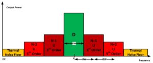
It can be seen that the first upper and lower adjacent channels are 3rd order intermodulation, whereas second upper and lower adjacent channels are 5th order intermodulation of the desired signal. DPD job is to reduce these 3rd and 5th order intermodulation terms, significantly.
That implies, DPD has to have control loop bandwidth in such a way to resolve the first and second adjacent channels in frequency, total 5x BW. By Nyquist sampling theorem that implies 10x BW of desired signal is required for DPD control loop.
Here is the summary of DPD challenges for 5G application, UWB:
- Memory effect of PA
- Run Time DSP computations of Predistortion signals
- Control Loop BW of DPD
The question becomes, are there alternative ways to linearize the PA output?
Partner with ORTENGA in 5G NR design and development.
Inquiry send to: info@ortenga.net
Posted on August 21, 2019
Why should you use FPGA for your prototype?
Field Programmable Gate Array, aka FPGA, allows startups to validate their design cost effectively.
The alternative is to implement the design in actual silicon which requires mask and fabrication of silicon. The mask could easily cost between 2 to 3 M$ depending on the technology, geometry, and the silicon fab.
Nowadays, startups and many established companies validate their design on FPGA before making any attempt to go for high volume production of silicon solution.
The following diagram illustrates the top level flow of FPGA design implementations and design validations.
ORTENGA not only has SME to support radio algorithms such as Power up Sequence, Automatic Gain Control, AGC, Automatic Frequency Control, AFC, Automatic Power Control, APC, but also can implement your proprietary design either via Linux or Embedded C platform of your choice.
Partner with ORTENGA in design, development, and implementation of your new product onto FPGA.
Inquiry send to: info@ortenga.net
Posted on August 18, 2019
5G Infrastructure Design Flow
5G infrastructure, aka gNB, design flow starts with Link Budget between gNB and UE.
Alternatively, one can rely on 3GPP Standards extraction related to gNB.
Once the Air Interface is extracted, it is prudent to validate some of the assumptions with potential customers. There are times that customers have additional requirements on the top of what Standards call for.
At this point, the Antenna Array Gain can be computed and the number of elements is decomposed.
The metric of interest is Eb/N0 or SNR for various conditions. One of these conditions is QoS, which can be BER and directly proportional to throughput.
The same design flow can be used in radar application with the only exception that in radar the Waveform is proprietary which is tailored to support dedicated use cases, whereas 3GPP Waveform is defined.
Partner with ORTENGA in design and development of gNB or radar design.
Inquiry send to: info@ortenga.net
Posted on August 17, 2019
Why should you use DOE in your System Design?
Design of Experiment, DOE, is a technique or methodology used to quantify the inputs and outputs relationship of complex systems.
In complex systems, there are many components and/or factors which contribute to the outcome and performance of the system.
Novice professionals take the Black Box approach to characterize and learn about the output to input inter-dependencies to either validate the design or debug any particular issue. Although, the black box approach could provide information about that relationship, typically it requires significant engineering resources and time to be executed.
On the surface, it is a sure thing, however due to significant required resources it typically misses the main contributors until it is too late. Black Box approach falsely assumes all components contribute uniformly to overall outcome. The idea of “all being equal” is based on having no insight into design fundamentals, and believing more tests are better even though some tests do not add value in solving the problem at hand. DOE is the technique to identify more valuable tests than others by evaluating the risk/pain point of the design.
By combing DOE and Perturbation Theory, many difficult problems can be solved.
Partner with ORTENGAto validate your new design prior to implementations during Critical Design Review, CDR, or after if you have difficulties in identifying an issue.
Inquiry send to: info@ortenga.net
Posted on August 15, 2019
What is application of Perturbation Theory in 5G?
Perturbation theory is comprised of breaking down a mathematical analysis to simpler forms of problems to be solved. The break down allows observing the impact of each component to overall solution. This is useful techniques that scientist and seasoned engineers utilize to evaluate their innovative solutions which have not been tried before and would cost valuable resources of time and money to experience sensitivity to each component.
5G NR requirements leads to many feasibility questions. ORTENGA uses perturbation techniques to analysis these requirements before actual design.
Partner with ORTENGA to design and develop your 5G NR.
Inquiry send to: info@ortenga.net
Posted on August 14, 2019
NB-IoT Applications and Classifications
Narrow Band Internet of Thing, NB-IoT, is one out of three 5G Use Cases, which will interconnect consumer electronics to internet. NB-IoT is the fastest growing market. NB-IoT devices will be approximately 50 billion by early 2020’s and will continue to grow.
The following diagram illustrates the applications and classifications of NB-IoT.
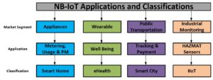
NB-IoT devices will have application platform on UE, so that the user can be communicate with any IoT device.
5G UE and NB-IoT devices will enable many new vertical businesses that do not exist today and will be available in few short years.
Partner with ORTENGA for design and development of your new NB-IoT device and technology.
Inquiry send to: info@ortenga.net
Posted on August 3, 2019
Why do you need Systems Engineering in your team?
Many startups and even NASDAQ 500 companies are trying to save cost by skipping Systems Engineering aspect of new product or project. It is simply assumed that one of the managers or higher authorities can specify the required components which are advertised by vendors. It is also assumed that by changing component down the line, any design short coming can be resolved.
The flaws in above assumptions typically cause manufacturability issues, i.e. scalability, which has direct implications onto cost of the product, in the best case scenario. In the worst case scenario, the product cannot be launched due to performance issues.
An example project is Fire Cell Phone with radio coexistence issue. It was over looked by the project leaders for lack of Systems Engineering’s due diligence until 2 years of engineering and materials investment and $170M later, it became obvious. Do the math, one or two Systems Engineering would have cost up to $500K for two years, but it would have saved $170M investment. The lesson learned is that the project leaders don’t save by skipping the most critical engineering process, which starts with Systems Engineering analysis, design, and trade-off study.
Needless to say, in the above example many prototype units had been built before releasing it to manufacturing and no issue was observed prior to product launch.
There is distinct difference between Prototype vs. Reference Design, using Commercial components of the Shelf, COST , which is not obvious if system analysis, gain/noise budget are not completed.
Partner with ORTENGA and we guarantee by identifying up to 5 issues with your radio and/or radar system design at no charge.
Inquiry send to: info@ortenga.net
Posted on August 2, 2019
Why should you be using MIMO Radar?
Traditionally radar waveform can be either optimized for spatial or speed resolution but not both. The new MIMO generation of radar allows multi waveforms operations. And each waveform can be optimized to specific interest in target. Nowadays, the applications for consumer products cover Autonomous Automotive, eHealth, and Smart City.
MIMO radar enhances time and frequency resolution of target. MIMO radar also improves SINR from signal echo. MIMO radar also mitigates in resolving Radar Ghost Target. These enhanced performances obviously come at the cost of engineering complexity. However, the current radar technology is catching up with design and development of transceiver and baseband IC to achieve such a performance.
Partner with ORTENGA for your new MIMO radar analysis, design, development, and image processing.
Inquiry send to: info@ortenga.net
Posted on July 31, 2019
Why Pioneer Engineers Develop their own Tools instead of using CAD?
Engineers, who work on innovative and out of box idea project in advance of the market, typically develop the necessary tools for simulations and/or metrology. Once, they design the tool, it has to be verified with actual measurements of real event. If the simulation tool predicts the real event closely, then there is no reason to change or switch to another simulation tool.
The success of these projects leads to recognition by market and traction for realization of similar industrial tools for others to follow. That is typically the time CAD tool vendors engage in designing and developing appropriate simulation platform. Obviously, there are some exceptions when there is collaboration between the Pioneers and Vendors for designing and developing simulations tool or metrology instrument in parallel.
Some CAD Tool vendors don’t get adequate traction for their Tool Boxes because of two fundamental reasons, namely; either they are late to market or the tool does not have adequate support from the get go. Their Marketing and Sales are not Subject Matter Export for promoting the Advance Tool Box capabilities and all potential use cases. And supporting R&D team will be last resort to help the customer when it is needed.
Partner with ORTENGA for your new product marketing services.
Inquiry send to: info@ortenga.net
Posted on July 30, 2019
COTS Prototype Pros vs. Cons
Commercial Off The Shelf, COTS, components expedite realization of a Prototype to validate a design and proof of concept. Therefore, the prototype can be demonstrated in front of potential customer or end user and seek valuable feedback which can be designed in for the actual product. That is why many start-ups with limited founding and time, choose COTS to build their prototype. This is simply a trade-off between prototype timeline vs. manufacturability.
Product development requires overall system analysis, architecture, and design. COTS allow pushing out the most of required design until there is adequate confidence about the idea and information about the market traction.
The issues arise, when it is assumed that the prototype based on COTS can be part of manufacturing line. When the start-ups want to duplicate many more units and sell to capitalize on the return of their investment, they first realize, duplicating a manufacturing line based on COTS is challenging. Their unit made on production line most likely has inadequate tolerances to meet the overall specifications, which impacts product yield. Second, product sourcing and cost could be another challenge as the result of yield as well as single sourcing. In other words, you cannot have reliable production line, if you cannot control the design and the part to part variations. Third, the product cannot be optimized using COTS, and typically have missing features which would have had created additional market traction.
In order to avoid these issues, the start-ups could architecture and design the system. The system engineer can document the requirements for every component in the system. Then evaluate both options; COTS and organic development of the prototype. At this juncture, they know the scope, cost, and challenges of developing the prototype. More importantly, they know the shortcoming of the COTS and the required technical performance. The shortcoming is analyzed and highlighted by the system engineer.
The startups can still go ahead with using COTS just to expedite the prototype, while they understand it would not be profitable and won’t be production line materials. At some point when they have adequate confidence on market traction, before it is too late, the startups can start the development of organic components such that when they are completed the manufacturing line is ready before market opportunity is lost. There is a difference between Prototype and Reference Design which must be understood by any startup which is planning to go to production. Skipping system design to expedite customer demonstration is a critical step for your product which cannot be compromised.
Partner with ORTENGA for systems architecture, design, prototype, and reference design of your new product.
Inquiry send to: info@ortenga.net
Posted on July 29, 2019
Apple 5G MODEM SoC
It has been known that Apple has being trying to design and develop mobile MODEM SoC over at least past 5 years without success. Apple dependency on iPhone is significant both financially and market recognition and branding. To maintain, the market share of smart phone and profits, Apple has two options. One option is to design an innovative device which is visionary, e.g. iPhone 1 in the world of flip or Blackberry phones. Second option is to reduce the BOM cost for existing product lines. It seems like Apple is taking the second option for now.
In the aftermath of Apple settlement with Qualcomm and Apple buying Intel mobile MODEM SoC business, there will be some changes for the industry as we know it.
It was known that one way or the other, Apple had to settles with Qualcomm over disputes as well as continuous shipment of Qualcomm chipsets. What Apple wanted in addition was to get a better deal and agreements over the royalty charges with Qualcomm.
So Apple proceeded with 2-prong approach, first it made agreement with Qualcomm over reduced royalties as well as continuous shipment for Qualcomm SoC for the next few years (estimated 3 years window from settlement time).
Then, Apple revealed and closed the deal with Intel for MODEM SoC mobile Business.
One more time, Apple has two sources for its iPhone MODEM SoC, Qualcomm and Intel (which Apple will own and run soon). Therefore, by the time Apple introduces iPhone XIII 5G compatible in September 2021, it can either slice the market based on carriers and/or geography. One thing is clear, Apple will have more leverage than before over its sourcing and supply.
With acquiring Intel Mobile MODEM SoC business and hiring many ex-Qualcomm engineers over the past 5 years, Apple also would be looking to have a place in future generation of MODEM SoC, e.g. 6G. In the business world, collaboration, competition, and cooperation go hand in hand for success.
Partner with ORTENGA for competitor evaluation.
Inquiry send to: info@ortenga.net
Posted on July 28, 2019
Operating Systems Classifications and Applications
There are five main operating systems, namely; Windows, Android, Linux, Embedded, and iOS.
The following diagram illustrates these operating systems classifications and applications.
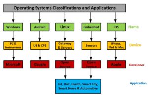
ORTENGA support services related to any of the above operating systems, in particular to emerging market segments for Internet of Things, IoT, Industrial IoT, IIoT, Smart City, Smart Home, and Automotive applications. ORTENGA services include Architecture, Segmentations, and Implementations for your new product.
Inquiry send to: info@ortenga.net
Posted on July 26, 2019
Product Conceptualization and Realization
Product conceptualization refers to an idea of a device, i.e. physical object, which provides certain function for at least one particular use case. The product concept is not adequate to realize any physical device and has to be further decomposed or partitioned to product definition. The product definition is a document which contains technical and quantitative blue print of the product at system level. The system level can be defined as what is used by the customer and/or end user.
The simple analogy of the product definition is a house architectural blue print. The engineering architecture designs and draws the house blue print which not only has physical locations of each room in the house but also it specifies all dimensions. Without the architectural blue print, you can still build a house, but it would not necessarily look the way you have imagined to be. There would not be a process, therefore associated timeline for each step of the way. Some hallway will be too small for furniture to be moved. The kitchen door may not be the right size to move in the refrigerator. Each window would be different size and has to be costume made, and so on. More importantly, without the architectural blue print, you cannot ask the general contractor to build a house for you.
On the other hand, if you are meticulous and build the house to your own satisfaction without a blue print, and someone else look at your house and ask you to build another one for them, you would not be able to duplicate what you built in the first place, at least not to the same level of details/specifications. In other words, without the architectural blue print, the house cannot be duplicated.
When you skip product definitions, basically you are making a prototype. Prototype is to validate the design or an idea. The prototype is not necessarily manufacturable with adequate yield, hence returning of you investment. Design For Manufacturability, DFM, is a process which takes into account the tolerances of various blocks or components in the systems, and specifies them in such a way that there is adequate yield in production environment. DFM is exercised by good and reliable manufacturers.
Lack of adequate product definitions, is typical issue at many startups that come short, even though they have a good technology, yet their product cannot be duplicated during manufacturing and they lose money for unacceptable yields.
Product Definition is an essential process of any product that you want to be able to manufacture and sell to make profits. It is the first critical milestone in the product design and development which cannot be overlooked or skipped. Systems Engineering job is to analyze the product concept and decompose that into Hardware, Software, and Firmware components level. Consequently, Systems Engineer documents the product definitions such that it can be built according to the specifications, which can be verified down the line. The progress of the product development can be tracked. Any gap can be identified before the product is completed and could be rectified or mitigated.
The following diagram illustrates any Product Conceptualization and Definitions before realization.
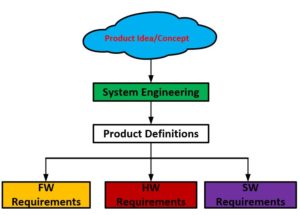
Partner with ORTENGA to analyze and systematically decompose new product concept into requirements and specifications for HW, FW, and SW which can be realized into successful product for market.
Inquiry send to: info@ortenga.net
Posted on July 25, 2019
What is an Edge Device?
Edge Device refers to a Fixed or Mobile device which is the edge of a network. The network could be a Cellular, SATCOM, Fixed Wireless, or WLAN.
Obviously each network has its own requirements, yet there may be some additional requirements which will be needed for Edge Devices. These additional requirements make the Edge Device unique from Architectural and Systems Design perspective.
In general Edge Devices have more capabilities and higher performance than a typical device for given application. For instance a wireless edge device is expected to have better receiver sensitivity, consequently better noise figure, as it is at the edge of network and being at margin of out of reach if the noise figure is not adequate. In addition, ad Edge Device may be required to do additional decision making which a typical device may not have to, due to proximity and access to the HUB.
Product definition is critical in success of the end product. Many products don’t see the market day light, even though the design and performance are meeting the specifications, just because the product definition lacks market traction.
Partner with ORTENGA in defining your new Edge Device product to succeed in the market.
Inquiry send to: info@ortenga.net
Posted on July 24, 2019
What are the differences between HW Prototype and Reference Design?
There are two types of HW projects; first Prototype, second Reference Design. They are both similar yet with somewhat different objectives.
In case of HW Prototype, although there is some analysis and simulation, but the functionality and performance of the HW has never been verified. This typically applies to out of box and innovative ideas and design validation which is required. HW Prototype is also used to characterize the design/device over Process, Voltage, and Temperature, aka PVT.
On the other hand HW reference design implies that there is confidence and supporting PVT data on the performance of the design, via HW Prototype. The HW reference design is final product that external customer can acquire and validate them on their own. The HW reference design is sometimes called the Evaluation Kit, aka Eval Kit. Customer gets Gerber and Schematic files as well as design guidelines for duplicating the reference design.
Partner with ORTENGA in your HW design, development, and Bring up.
Inquiry send to: info@ortenga.net
Posted on July 23, 2019
Margin vs. CE Product Delivery to Market
New technology and/or innovation bring about many Consumer Electronics, CE, Products into the market. The following diagram illustrates typical margin vs. first, second, and 3rd companies who succeed introducing the new product.
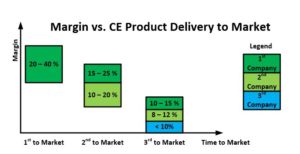
The first company which introduces the successful product into the market, has visionary leaders and/or entrepreneurs who understand the market requirements before anyone else and take calculated risk to design and develop a new product without knowing whether it would succeed or not. Market rewards their risk by providing a healthy margin while they are the sole producer in the market.
The second company which produces the similar product into the market typically reduces that healthy margin for the first company, yet still can make adequate double digit margin.
The third company has an additional impact on margin for first and 2nd company and drops the margin further for everyone.
Time To Market, TTM, is critical metric for success of any new product, margin, as well as Return of Investment, ROI, over the duration of the product life cycle. The longer the time between the 1st and 2nd companies’ new product introduction, the more return the 1st company enjoys with that healthy margin. That is why successful entrepreneurs and businessmen strive to be first into the market.
If you delve into what is behind or what it takes to be the first into the market, you will realize that there are three main contributors; namely,
- Visionary Product Definition by Systems Engineering
- Calculated Risk Taking by Entrepreneurs who appreciate the System Engineering product definition
- Engineering execution of the product design and development by the Company Leaders
If your company wants to make healthy margin of your new product, partner with ORTENGA in product definition.
Inquiry send to: info@ortenga.net
Posted on July 20, 2019
Glucose Detection and Measurement
Glucose aka sugar is an important source of energy in living organism. Regulating the Glucose level in the body, which is essential contributor of one’s health, is of prime interest in the medical application. There are three known technique to measure the Glucose level in one’s body, via Blood, Eye, and/or Sweat tests.
Blood test is known to be the best way to measure Glucose level as you may have seen on your annual physical test. It is an invasive technique to draw blood and assess the Glucose level. There are many handheld devices that allow the test by end users on periodic basis.
Eye test is fairly non-invasive technique that optically assesses the Glucose level. You may have experienced that when you visit your Optometrist on annual basis.
Alternative way to measure Glucose is by testing human body sweat. This is non-invasive technique which is preferred by end users. Many companies are working toward design and development of wireless technique to measure Glucose via human body sweat.
Market traction and opportunities are tremendous for Glucose Sensor and Measurement for mobile UE devices.
Partner with ORTENGA for product definitions and component requirements for Glucose detection and measurement device.
Inquiry send to: info@ortenga.net
Posted on July 19, 2019
OneWeb LEO UT Prototype Architecture
OneWeb has started validating the LEO UT Prototype based on Intellian MSA, SatixFy RFIC and SoC HW. The following diagram is simplified OneWeb LEO UT Prototype Architecture.
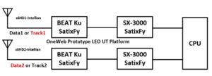
It is not clear whether these components reflect final design, yet are utilized to validate the Radio Link Budget as well as LEO DL Throughput.
Partner with ORTENGA to analyze LEO SATCOM Link Budget, identify Radio Front End, Transceiver, and MODEM chip sets/vendors, and design HW with down selected ASICs and appropriate algorithms to control beamforming architecture for your mobile product.
Inquiry send to: info@ortenga.net
Posted on July 18, 2019
Amazon LEO SATCOM Payload Architecture
Kuiper Systems LLC, subsidiary of Amazon, has filled FCC application for Satellite Space Station Authorization on July 4, 2019.
Based on the application, it appears that Amazon prefers and down selects traditional/legacy Phased Array Architecture for LEO Satellite. This entails costly radio front end as well as required calibration to overcome P.V.T. and associated operational algorithms.
Given that, should they opt for traditional Bent Pipe instead of On Board Processing payload, it would be the bottle neck for Eb/N0and/or LEO DL Throughput.
Partner with ORTENGA to analyze LEO SATCOM Link Budget, identify Radio Front End, Transceiver, and MODEM chip sets/vendors, and design HW with down selected ASICs and appropriate algorithms to control beamforming architecture for your mobile product.
Inquiry send to: info@ortenga.net
Posted on July 11, 2019
The Art of Triangulation Location Finding
Location finding of mobile UE in radio network has become ubiquitous feature with multiple use cases.
The art is to triangulate the UE as accurate as possible. The triangulation means determining the timing measurements from at least 3 reference points and calculating the distance from these points to locate the UE.
The following diagram illustrates triangulation of UE by three cellular sites.
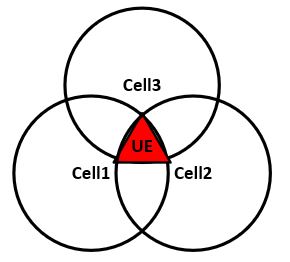
In practice, it boils down to detecting signals from the Cellular Sites, estimating the relative timing based on the signal strength and estimation of appropriate part of the sub-frame of cellular packet format/protocol as well as digital signal processing algorithms which are based on statistical analysis.
The calculated location of the UE would be to within a “Triangle”, or uncertainty. The smaller triangle the better the signal detection and/or algorithms.
Partner with ORTENGA for location finding HW/Algorithm design and development.
Inquiry send to: info@ortenga.net
Posted on July 2, 2019
Debugging and Design of Experiment, DOE
In the field of radio communication systems engineering, there are many times where the system has to be debugged to diagnose an issue and to be addressed.
In order to debug any system, there should be a mapping between failure signature/symptom and potential sources/contributors to that issue. To draw that mapping, it requires understanding of actual systems design, RF impairments and requirements.
That mapping of symptoms to potential sources should be done by radio communications systems engineer with insight to overall design. Typically, for any issue, there are many sources that could independently and/or collectively cause that issue. To verify and test for each condition, it would be time consuming and resource intensive, i.e. expensive.
Radio Communication Systems engineer will be able to look into the design requirements/specifications and rate or access the risk of occurrence of potential issue and prioritize the verification of parameters to be tested. That priority list which is based on risk assessment is called Design of Experiment, DOE.
DOE saves resources and time to get to the root cause.
Partner with ORTENGA to debug and root-cause any system issue you are facing before launch of your new product.
Inquiry send to: info@ortenga.net
Posted on June 28, 2019
Does an amplifier help improving the signal to noise ratio?
RF Engineering profession has many pitfalls for new comers or those who don’t have adequate education or experiences. One of the first pitfalls encountered by many who are new to RF engineering, is in a system where the signal to noise ratio, SNR, is weak and inadequate, adding an inline amplifier. Their expectation is to increase SNR by adding some gain via the amplifier.
It would become clear, if tried, that the inline amplifier does not discriminate the desired signal vs. undesired signal/noise, i.e. the amplifier cannot tell the difference between signal and noise. Therefore, both signal and noise get amplified at the same rate, dB per dB, therefore not only the SNR does not improve going through amplifier, but also the output SNR of the amplifier would degrade relative to the input SNR, due to added noise by the amplifier.
Inquiry send to: info@ortenga.net
Posted on June 27, 2019
5G Health Concern
ORTENGA has received many requests to look into 5G Health concern of this new technology. Although, ORTENGA does not provide consulting services of the impact of 5G electromagnetic waves on biological tissues and human interaction, ORTENGA is sharing information with consumers and its clients, so that they can be in better position to make the judgement themselves.
What we don’t know?
Since 1970’s, although many researches have been conducted to assess the impact of electromagnetic fields and/or radiation on human body and/or tissues, there is no concrete conclusion of that impact or interactions. Regardless, there is working equipment which can be used to assess cause and effect in systematic and/or scientific manner.
What we know
Let’s delve into some of the equipment and discover how they interact with human body in statistical sense. By Statistical sense, it is meant that although human body is complex and does not necessarily every individual (considering race, gender, age, state of minds, etc.) have the same response to various stimuluses (in this case electromagnetic fields) but overall most of the population under the study would have the same/similar reaction.
Human body response to Electromagnetic fields and waves depends on:
- Frequency of operations
- Strength of the Electromagnetic fields
- Whether it is soft or hard tissue
In other words, safety of exposure to electromagnetic radiation depends on all of the above. Consequently to draw any scientific conclusions all of the above metrics have to be considered and tracked for any meaningful case study.
Frequency of Operations
Radio waves are anywhere between KHz, e.g. AM radio, way below 1GHz, to RF1 up to 6GHz, and into mmW bands up to 60GHz, 802.11ad/ay.
The changes in operating frequencies are ~8 orders of magnitudes, i.e. 108 or 100 million times differences. That is significant range of operating frequencies, AM radio to mmW into 60GHz, and nothing that we know of behaves in the same way over that extreme wide frequency range, equipment and/or human body. Therefore, let’s breakdown the radio waves operating frequency to the following use cases and evaluate case by case.
Use Case 1: Magnetic Resonance Imaging, aka MRI, equipment used for imaging of soft tissues is typically operates at 1T or 1.5T in case of Human subjects. One Tesla, 1T, is equivalent to 10000 Gauss, G. Earth magnetic field is 0.5G, to put Tesla unit into perspective.
About 75% of human body weight is comprised of water. The resonance frequency of water is function of magnetic field strength. Resonance frequency can be considered the frequency at which the water molecules have tendency to oscillate naturally.
The relationship between human body soft tissue resonance frequency and magnetic field strength is per following:
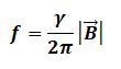
Where, B, f, and gama are Magnetic field, frequency, and Gyromagnetic ratio, respectively.
Therefore, 1T and 1.5T magnetic fields yield 42.xx and 63.yy MHz operating frequencies, respectively. Observe that as the magnetic field increases the water resonance frequency also increases with direct proportion.
In other words, for imaging soft tissues, e.g. muscle, brain, internal organs, the MRI equipment operate at ~42 or ~63 MHz. The impact to human body is known to be negligible so long as the body stays stationary inside the MRI magnet. In case of movement inside of the MRI magnet, there is Eddy Current generation that could potentially harm and cause in comfort to the patient. Therefore, there is trade-off between a non-invasive imaging to diagnose any potential issue versus minimal risk to put the body under strong magnetic field for duration of the test only.
Use Case 2: 802.15.6 is Standard which addresses Wearable sensor for human body applications. Although the allocated operating frequency covers 2.4GHz ISM band, but the lower frequency edge is 20 MHz, which is known to be providing better coupling between the sensors and human body.
Use Case 3: Cellular phone operating frequencies are typically between 1 – 2 GHz. The strength of the cellular phone electromagnetic radiation must be less than 1.6W/Kg per FCC regulations. Human head weights about 4.5 to 5 Kg. The maximum permissible operating power of the cellular phone is ~23dBm, 250mW, or 0.25W. This is the amount of transmitter power in the case the cellular phone being at the farthest location from the nearest cellular base station which provides connectivity, a rare/edge scenario. These numbers are calculated for impact to the user of the cellular phone and don’t apply to second hand individual near to another user. Also, we are mixing near field, user’s head proximity, with far field radiation, just to have some baseline for this calculation. Typical operating point of cellular phone is around ~10mW, or 0.01W. Therefore, human head exposure to electromagnetic energy to be transmitted to the base station is numerically very low, compare to FCC regulations. Incoming phone calls power to the cellular phone are typically between -80 t o-100 dBm, which are 90 to 110 dB below the typical cellular phone in transition mode. 90 and 110 dB below power means 1 down to 1/100 billion times smaller, respectively. In other words, the worst case radiation is when one is transmitting via cellular phone, i.e. receiving mode is much more benign.
The question still remains are these levels of exposure safe for human at the operating frequencies of cellular phone.
Based on the Example 3 calculations, it is safe to assume the exposure of electromagnetic radiation to nearby or bystanders’ people (i.e. not the person who is using mobile phone) are way below FCC regulations. We don’t know if that is safe, but we know it is low relative to FCC regulations.
In other words, if you don’t believe cellular phones are safe, so long as you are not the one using them, you can safely assume to be statistically unharmed if other people use them.
Use Case 4: Hyperthermia or Heat Treatment is a technique which some Oncologists utilize to decelerate or destroy/kill cancer tumor non-invasively using electromagnetic radiation pointed only at the malignant tumor cells. By increasing the blood flow and temperature of the tumor cells to about ~44°C, the human cells are dying.
Hyperthermia equipment is typically operating between 100 – 900 MHz operating frequency range. The optimum frequency depends on the volume of the tumor. For instance, for 3 – 4 cm3 tumor the optimum frequency is ~450 MHz. It is also well known that higher frequency provides better spatial resolution, i.e. more focused energy into the tumor and not its vicinity. The trade-off is between better spatial resolution and less power/energy penetration/absorption for/by the tissue.
Use Case 5: 5G RF2 is in mmW bands, at 24, 28, and 39 GHz. The mmW bands are near water molecules absorption frequency in gas or moisture in the air. It is well known at these frequencies; the Atmospheric Loss, AL, becomes significant in communication link between transmitter and receiver, i.e. less power is received by intended receiver for given transmitted power.
The following is AL in GHz spectrum range published by FCC, Bulletin Number 70, in July 1997.
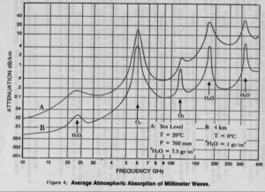
The mmW power transmitted decays much faster over the air; consequently the range (the maximum distance between transmitter to receiver) is significantly shorter. This in turn dictates that transmitter power cannot be indiscriminately (in all direction) radiating for any useful purpose and requires pointing the energy/power to desired direction, i.e. actual end user.
5G will be relying on beamforming techniques to point the energy of the transmitter directly at the end user, receiver. Therefore, by standers will not be receiving any radio wave energy. In fact beamforming is part of 3GPP and 802.11ad/ay Standards, which operate in mmW bands, because of AL.
The beamforming is the technology which dynamically points the transmitter energy to mobile receiver in much less than seconds interval. In doing so, the receiver and transmitter are in continues communication about each other locations. The radiation pattern is pencil beam with couple of degrees Half Power Beamwidth, HPBW. To appreciate the directivity of pencil beam transmitter to receiver, you can touch your satellite dish slightly to move it, and you will be losing the signal completely (don’t do this, if you do not have adequate equipment and skills to put the satellite dish pointing back in the original direction).
5G technology is expected to be scalable for requested user data and availability of network. That means, if you are doing a voice call in 5G networks, you are not necessarily using 5G infrastructure for your call to go through, because that would be wasting significant radio network resources, and your call may be scale back down to legacy voice network with current networks.
Conclusions
The point is that if you are not the one who is having and using 5G or 802.11ad/ay new WiFi devices in mmW, then you are not being illuminated by 5G or 802.11ad/ay new WiFi transmitter.
That is not necessarily true about 4G/LTE, 3G/CDMA, 2G/GSM, 1G/AMPS, and legacy WiFi networks. In other words, 1G/2G/3G/4G, and legacy WiFi networks illuminates everyone in their coverage area regardless whether they are the actual end user for radio wave communications, whereas 5G networks illuminate the end mobile user.
MRI, Hyperthermia, and Wearable equipment focus below 1GHz operating frequency range, where actually coupling of electromagnetic energy into the human body is intended. As the frequency increases, the atmospheric loss of transmitted signal and penetration into human tissue decreases.
The mmW bands (well above 1 GHz) signals have much less penetrations capability into human body and have significant loss through air relative to sub GHz bands.
In light of the above, can we say that 5G is safe technology?
What we could conclude is that 5G technology would not be any less safe than 4G/LTE, 3G/CDMA, 2G/GSM, and/or 1G/AMPS communication networks, while the service is used appropriately.
If you are not convinced on health safety of previous mobile communication generations, then you should continue your research for additional information to make appropriate conclusions.
ORTENGA is consulting firm which provides design and develop algorithms and HW modules, or customer specific projects in the field of wireless communications.
Inquiry send to: info@ortenga.net
Posted on June 24, 2019
What is an Algorithm?
An algorithm is a set of rules, step by step, and/or process for completing a very specific task.
In High tech industry, within the invention of any machine, automate piece of equipment, always if not many, at least one algorithm is used for expediting the execution of sequence of an event.
In particular, Wireless Communication Systems industry uses many algorithms to accomplish and maintain functionality as well as performance of your wireless device, phone, laptop, microwave oven, etc.
ORTENGA subject matter experts design and develop algorithms, such as but not limited to Automatic Gain Control, AGC, of transmitter and/or receiver chains, aka transceiver, synchronization between transmitter and receiver, calibration of RFIC, RF impairment estimations and corrections, controlling beamforming of a Software Defined Antenna.
Whether you use ASIC devices from vendors or you design and develop ASIC which needs to interface with multiple devices within the HW systems environment in any Wireless Applications and Standard, ORTENGA can develop appropriate algorithms to meet the requirements.
Inquiry send to: info@ortenga.net
Posted on June 18, 2019
802.11ay, Next Generation WiGig Packet Format
802.11ay is the next generation of WiGig, aka 802.11ad, with mission to enable Augmented Reality, AR, and Virtual Reality, VR, and wireless backhauling applications.
802.11ay will enable 100Gbps connectivity for short range by utilizing MIMO, Channel Bonding, improved channel access, and enhanced beamforming training.
The following diagram illustrates 802.11ay packet format.

802.11ay packet, Enhanced Directional Multi Gigabit aka EDMG, is expected to be backward compatible to 802.11ad, aka Legacy, L, in the above diagram.
Partner with ORTENGA for designing and developing mmW Beamforming radio communication architecture and systems.
Inquiry send to: info@ortenga.net
Posted on June 17, 2019
Top Skills for Project Ownership and Leadership
In high tech industry, there are some organizations which accomplish the project in hand and become successful. On the other hand, there are other organizations which face challenges in accomplishing their own goals. There are distinct differences between these organizations which can be spotted and perhaps mitigated if the issues are acknowledged, highlighted, and addressed before valuable resources such as; time, engineering, and funding run out.
The success of technical projects depends on three factors. First, the project must be scoped out properly, after the project leader has been assigned to it. The project owner/leader has to learn about the necessary milestones, draft a plan and timeline to accomplish them within the first two months in to the project. The necessary milestones could be anything that needs to be accomplished for at least any next six month down the road in to the project.
Second, the project owner/leader has to access the required engineering skills for taking on the project. That requires understanding the milestones dependencies as well as fair amount of knowledge of about doing them. Not having appropriate engineering resources delays and prolongs at minimum and eventually leads to stagnant in achieving any meaningful milestones.
Third, the project owner/leader has to access the required equipment which will be needed for engineers to accomplish their tasks in achieving the milestones. Good engineers may/can come up with innovative ideas to overcome lack of proper tools, by trading fair amount of time to design and develop the required tools. If the project is time sensitive, then having proper tools could be critical.
Anyone whom does not possess at least two out of three of the above skills, will be setup for an impossible challenge at the best, most likely, s/he would be not realizing the challenge in hand until the significant time, most valuable resource, is elapsed before acknowledging or being reminded of by the market opportunities squandered.
Someone, who possess and understanding of first and second of the above skills, will have engineering resources that can lead through and find out about the third, still, s/he would be facing challenges which will test his/er resolve, only succeed if willing to learn the missing third item along the way.
Obviously, someone who possess all three of the above, will have adequate resources at his/er disposal and in best position to address technical challenges in the face of project before accomplishing it. If you want guarantee success of your project, then you need leader with not only the fundamental 3 attributes but also with vision which can see beyond the next 6 to 12 months and onto 1 year or 2 years out.
Successful organizations and top executives are aware of these top skills requirements. They seek, identify, and select project leaders with all three attributes, and may compromise only one out of three. Program managers can help in filling the gap of the missing item.
Best teams are comprised of top quality leader as described above, program manager, appropriate engineering and equipment. They are prepared to weather the challenges and overcome them.
ORTENGA is comprised of Subject Matter Exports in Radio Communication Systems, Digital Signal Processing, Software Defined Radio, Software and Firmware Drivers who can provide services to your project success.
Inquiry send to: info@ortenga.net
Posted on June 15, 2019
Why On-Board Processing Satellite Payload will be enabling LEO?
Legacy GEO satellites non-regenerative, aka Bent Pipe Payload technology, were designed based on the constraints and requirements of 1960 – 2010 to save Size, Weight, and Power, SWaP, which ultimately impact cost.
Over the past two decades, the need for higher data capacity has grown significantly, from few hundreds Kbps to tens of Mbps, and continuing even steeper trends for the next decade.
Over the same period, the semiconductor geometry has decreased from 0.130um down to 7nm CMOS technology for digital signal processing at baseband. The electronics’ power consumptions have also been reduced by implementing Sleep and Awake circuitry for the time of use, while reverse saturation current been directly proportional to the geometry.
Data capacity is dictated by Shannon Theory and is proportional to bandwidth and power, which are governed and restricted by FCC and ETSI.
In order to achieve higher throughput in the LEO SATCOM, architecture and system designers are taking a fresh look at new as well as legacy constraints and requirement to innovate alternative solution which addresses today’s consumer electronics product.
On Board Processing Payload allows the retrieve of data at satellite payload, which would remove/diminish satellites’ C/N and C/I dependency in the overall LEO Link Budget, consequently increasing the overall Eb/N0, hence better data throughput.
On Board Processing Payload not only has become possible, but also necessary to meet required data throughput for the next decade. LEO Payload satellites are being designed and developed with this new technology.
Partner with ORTENGA in designing the architecture and systems of LEO SATCOM products.
Inquiry send to: info@ortenga.net
Posted on June 14, 2019
Regenerative LEO Satellite Payload Architecture
As LEO satellites designed and launched, some are based on legacy Bent Pipe Architecture and others are utilizing Regenerative, aka On Board Processing Payload Architecture. Regenerative LEO satellite architecture is more complex with the advantage of additional throughput relative to Bent Pipe system.
The following diagram illustrates top level Regenerative or On Board Processing LEO Payload.
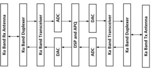
Design of the LEO payload requires analyzing and decomposing the system requirements to component level which will satisfy the overall expected throughput during the operation. It would, then, require down selecting appropriate vendors with specified semiconductor ASIC, designing HW with selected components, validating the design system level requirements via DOE before launching the payload.
Partner with ORTENGA in design and development of your LEO SAT Payload and/or LEO UT.
Inquiry send to: info@ortenga.net
Posted on June 12, 2019
LEO SATCOM Beam Sequencing Requirements
In contrary to GEO satellites where they are in the orbit geostationary with respect to Earth, LEO satellites are passing by User Terminal, UT, every 10 – 20 seconds depending on the their altitude, the number of satellites in each orbital plane, and network coverage plan. Therefore, LEO UT must be able to Beam Sequencing in very short period of time to track the moving LEO satellites while they keep connectivity with the satellites. Consequently, the UT must either mechanically or electronically sequences its beam to keep the connectivity while it is tracking one satellite and hop to another moving satellite when the first satellite is out of sight. This has implications on the how fast the beam has to form and on the technology of the beam steering mechanism.
Partner with ORTENGA to design and develop LEO Satellite or UT product.
Inquiry send to: info@ortenga.net
Posted on June 9, 2019
LEO UT and 5G gNB Beamforming Options
Beamforming is becoming ubiquitous in LEO UT and 5G gNB electronics. The history of beamforming can be traced back to 1960’s in Phased Array Antennas.
The following diagram illustrates the progress of beamforming technologies and engineering complexity over the past ~70 years.
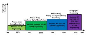
It can be seen that beamforming started with Antenna and RF engineering in Analog domain, hence ABF. To address some of the issues seen in Digital domain by later feasible technology, DBF was born. A decade later, Hybrid Beamforming, HBF became the optimum technology for large arrays of antennas.
Nowadays, Holographic Beamforming, HGBF is the trend for many applications. It worth to mention that HGBF is still new and cross functional engineering discipline must be involved to design successful product for LEO UT and/or 5G gNB electronics, where Systems Engineering, SE, is at the heart of the efforts to put together that intricate engineering product.
Part of engineering complexity comes about the operation of these technologies in actual field when there are unit to unit, i.e. Process, Voltage, Temperature, aka PVT variations and these electronics must maintain the adequate level of performance to be useful.
The following diagram illustrates high level integration capability vs. characterizations and calibrations needed before actual field operations.
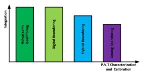
There are some practical metrics, such as Cost, Power consumption, Size, and Weight that play roles in deciding whether to integrate any technology into a product.
The following diagram illustrates the level of Cost vs. Power, Size, and Weight of the beamforming technologies.
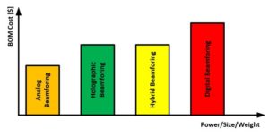
Let us know how ORTENGA can be part of your design and development of new radio technology.
Inquiry send to: info@ortenga.net
Posted on June 1, 2019
SATCOM Coding
The following diagram illustrates SATCOM concatenated coding architecture used between Satellite and UT.
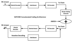
It is well known that Viterbi coding causes burst errors and RS coding is capable of removing several error simultaneously, therefore concatenated Viterbi and RS coding is a natural choice for SATCOM applications. Adding coding, error correction of digital signal enhances the radio communication performance by reducing the required transmit power for given BER, i.e. QoS, and/or increasing the range.
The tradeoff is in Latency as well as receiver decoder complexity and its implementation in the SoC.
SATCOM is utilizing concatenated coding architecture in which 2 layers of known coding are providing enhanced error corrections to reach QEF.
Let us know how ORTENGA can help in design and development of your radio communication systems.
Inquiry send to: info@ortenga.net
Posted on May 27, 2019
5G Concatenated Coding Architecture
It is well known that by adding coding, error correction of digital signal enhances the radio communication performance by reducing the required transmit power for given BER, i.e. QoS, and/or increasing the range.
The tradeoff is in Latency as well as receiver decoder complexity and its implementation in the SoC.
5G is utilizing concatenated coding architecture in which 2 layers of known coding are providing enhanced error corrections with known decoding algorithms.
The following diagram illustrates 5G NR concatenated coding architecture used in UE.
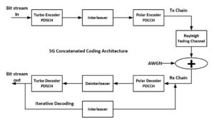
Let us know how ORTENGA can help in design and development of your radio communication systems.
Inquiry send to: info@ortenga.net
Posted on May 24, 2019
Wearable Technology
With the introduction of 5G mobile handset into market, there are many new features that can be sought of. One of these new features is sensor technology that provides health and/or well-being monitor of the user. This technology idea is not new and being used in space programs since 1960’s. However, now it is becoming part of commercial applications.
Apple, Adidas, Google, Nike are among many more mid and small size companies which are designing and developing consumer products with embedded Wearable technology in to their product lines.
All of these Wearables utilize wireless connectivity, i.e. radio, to transfer data from the sensor, e.g. human breathing, pulse, sweat, organ’s information to mobile handset device for further analytics and display.
Partner with ORTENGA to capture constraints and requirements into appropriate product definition before designing and developing your new Wireless Wearable product.
Inquiry send to: info@ortenga.net
Posted on May 18, 2019
What are Radio Link and Line-up Budgets?
Radio communication link between any transmitter to receiver needs to be designed for:
- Transmit Power
- Range between the transmitter to intended receiver
- Signal to Noise Ratio, SNR and Eb/N0
See figure 1 below.
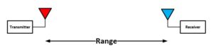
Figure 1: Radio Communication Link
Radio communications systems like 4G, 5G, WiFi/802.11, BT, 802.15, LEO SATCOM, radar, microwave links all have Link Budget. The Link Budget is more than just the engineering analysis and system design, it also impacts the bottom line via systems throughput.
Keep in mind, given 5G Standard, that does not imply the Link Budget is unique and the same for every system. It depends on the constraints and use cases for your particular application.
That communication link depends on additional parameters such as:
- Wavelength or operating frequency
- Transmit antenna
- Receive antenna, i.e. G/T
- Characteristics of the receiver, Line-up Budget
- Whether it is Line of Sight, LOS, or Non Line of Sight, NLOS
- Objects between the transmitter to the receiver, natural or man-made, which cause fading
- Modulation and Coding Scheme, MCS, i.e. required BER and Eb/N0
- Whether there are any other Radio nearby, i.e. radio coexistence or interference by other users
Once the Link Budget is analyzed and determined the required transmit power, range, and receiver SNR, then the Line-up Budget must be done to design that transmitter and/or receiver.
The Line-up Budget is the analysis that determines the required component specifications which are needed to meet the Link Budget, see figure 2 below.
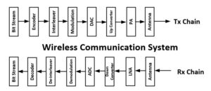
Figure 2: Typical Radio Transmitter and Receiver
The Line-up Budget consists of thermal noise, phase noise, quantization noise, I/Q imbalance, non-linearity, dynamic range, overhead, AGC, Exact number of bits analysis for the overall system.
Each component in the radio front end must be defined in a way to meet the required noise and unwanted signal level at its input as well as output. In other words, the SNR is not constant and is function of the each node and dependent on the component selection and performance.
Keep in mind that if you expect your radio to work under any environmental circumstances, then all of the above analysis and component selections must work over Part to Part, Voltage, Temperature, aka PVT variations.
Not all of vendors’ component will meet the Link and/or Line Budget of your system; that is what differentiates any radio system from another, a prototype against robust radio.
The difference between prototype radio and a robust radio is not about functionality of the radio, it is about maintaining the performance of the radio under all of the above environmental variations and in presence of other users which interrupt the radio performance if it is not properly designed and budgeted. The robust radio meets end user need in actual environment, whereas the prototype radio demonstrates functionality under limited conditions.
Various Standards require different architecture, system analysis, and appropriate components’ selection.
Partner with ORTENGA for your new radio systems design and development. ORTENGA provides architectural, system analysis, design, and validations to meet the end user requirements based on your constraints and requirements.
Inquiry send to: info@ortenga.net
Posted on May 13, 2019
Which Waveform should be utilized for LEO SATCOM, DVB-S2, 3GPP, or CDMA Waveform?
Commercial GEO SATCOM MODEMs are based on SoC DVB-S standard. On the other hand, CDMA waveforms are utilized for Governmental and Proprietary GEO applications.
LEO SATCOM application is targeting higher throughput and feasibility studies and simulations are being done to look for alternative waveforms which are more spectrally efficient. One of these waveforms is 3GPP LTE and/or its derivatives.
Both CDMA and LTE waveforms provide higher sensitivity MODEM relative to DVB-S2. Additionally LTE MODEM can support higher bandwidth and spectrally more efficient at high SINR, MCS13/14/15, than CDMA. LTE SoC MODEM and appropriate test equipment are also available in the current market. Many companies are working to tailor and optimize new family of LEO SATCOM SoC MODEM.
Partner with ORTENGA to down-select appropriate MODEM SoC for your new product.
Inquiry send to: info@ortenga.net
Posted on May 11, 2019
LEO Down Link
According to FCC regulations for Satellite EIRP, PFD on Earth, and analyzing, LEO Ku band User Terminal, UT, DL can have better than 10dB Eb/N0. By adding 8dB Turbo coding gain, that is ~18dB, conservatively. In other words, UT DL link can operate up to 256QAM Modulation and Coding Scheme, MCS, with existing MODEM SoC in the market.
The frequency reuse could be eight 250 MHz DL Channels for users in Ku Band, 10.7 – 12.7 GHz. Therefore the antenna requires 2 GHz bandwidth, albeit it could be dynamically tunable. Each of these 250 MHz channel is divided into multi access depending on the BW allocated by the network for each user. The user band selection occurs in the digital domain via MODEM SoC time slot partition. That is each UT process the 250 MHz band through RFFE and in the MODEM the data parsing and dedicated user data is selected.
Partner ORTENGA in designing and developing of your LEO SATCOM User Terminal. ORTENGA will work with you to define Throughput/Availability of Network Resources, Assignment of Resources to each Customer, Coordination of Spectrum with regulatory organizations, FCC and ETSI, and other users of the spectrum, Optimization of Link budgets and System Trade-Offs. ORTENGA will down select components such as SoC MODEM and Transceiver RFIC and required filtering which account for Thermal, Phase, I/Q imbalance, Nonlinearity, and Quantization noise, and Top Level Architectural documents for the Wireless System, AGC Algorithm and Gain Line up.
G/T
What is the importance of G/T ?
G/T stands for receiver Antenna Gain to Thermal Noise ratio. It turns out that C/N is directly proportional to G/T for any receiver. Therefore, the data rate or throughput is directly proportional to G/T.
For instance in SATCOM link, the receiver C/N reference to antenna terminal is directly proportional to G/T.
By carefully looking into the G/T metric, it becomes clear that just optimizing the antenna for its gain does not necessarily yields to a better C/N, as there is a trade-off between antenna gain and its thermal noise. Consequently, G/T is the metric to be optimized during antenna design.
Antenna temperature is function of its physical and brightness temperatures, as well as radiation efficiency.
Appropriate systems and architecture design takes into account the trade-offs and inherent relationships between these metrics to arrive at appropriate link budget and system behavioral model for computing C/N and throughput.
Partner ORTENGA for feasibility study, designing, and/or developing of your new radio communication systems architecture and definitions.
Inquiry send to: info@ortenga.net
Posted on May 5, 2019
LEO Link
LEO Down Link
According to FCC regulations for Satellite EIRP, PFD on Earth, and analyzing, LEO Ku band User Terminal, UT, DL can have better than 10dB Eb/N0. By adding 8dB Turbo coding gain, that is ~18dB, conservatively. In other words, UT DL link can operate up to 256QAM Modulation and Coding Scheme, MCS, with existing MODEM SoC in the market.
The frequency reuse could be eight 250 MHz DL Channels for users in Ku Band, 10.7 – 12.7 GHz. Therefore the antenna requires 2 GHz bandwidth, albeit it could be dynamically tunable. Each of these 250 MHz channel is divided into multi access depending on the BW allocated by the network for each user. The user band selection occurs in the digital domain via MODEM SoC time slot partition. That is each UT process the 250 MHz band through RFFE and in the MODEM the data parsing and dedicated user data is selected.
Partner ORTENGA in designing and developing of your LEO SATCOM User Terminal. ORTENGA will work with you to define Throughput/Availability of Network Resources, Assignment of Resources to each Customer, Coordination of Spectrum with regulatory organizations, FCC and ETSI, and other users of the spectrum, Optimization of Link budgets and System Trade-Offs. ORTENGA will down select components such as SoC MODEM and Transceiver RFIC and required filtering which account for Thermal, Phase, I/Q imbalance, Nonlinearity, and Quantization noise, and Top Level Architectural documents for the Wireless System, AGC Algorithm and Gain Line up.
Inquiry send to: info@ortenga.net
Posted on May 4, 2019
Successful Electronic Consumer Product
Successful electronic consumer product can be introduced in to market and become common name within its first year of introduction. Looking back for example, iPhone (smart phone), Thumb drive (USB memory) are good examples. Now they are must have for anyone in high tech industry and doing business within electronic industry.
How did the original version got to be recognized by consumers?
- Identify the need/pain point.
- Out of Box product was conceptualized.
- Technical feasibility was verified.
- Appropriate components and vendors were selected.
- Diligent works were done to build the new product prototype.
- Manufacturability of the prototype was analyzed.
- Production was launched.
In all of the above, it is outward looking and taking calculated risk. If your company is not willing to invest on new ideas, then don’t expect disruption.
Disruption requires systems engineering with vision and business acumen to architect any successful electronic consumer product.
Partner with ORTENGA to conceptualize, architect, and design appropriate system to realize your new radio product.
Inquiry send to: info@ortenga.net
Posted on April 30, 2019
The impact of Antenna Efficiency on Antenna Temperature
Radio Communications Systems Engineers budget the noise impairments of each block in the system to limits it and design for adequate SINR. In spite of that, there is not much can be done to limit the noise contribution of the antenna itself, so it must be well understood before claiming design completion.
Antenna noise temperature is function of physical and brightness temperature. The physical temperature of the antenna is dictated by the antenna surrounding or ambient temperature.
Brightness temperature is the temperature that is seen by antenna based on its radiation pattern as well as environmental condition, profile or distribution of background temperature.
For instance, if the background temperature is constant, then the brightness temperature is background temperature. In SATCOM, the brightness temperature is not constant and depends on the pointing angle of the UT antenna.
As the antenna efficiency increase, the antenna temperature can converge to brightness temperature. In fact, if the radiation efficiency is 1, then antenna temperature is brightness temperature. On the other hand, when the radiation efficiency is zero, the other extreme, the antenna is a matched load and the antenna temperature is its physical temperature.
Partner ORTENGA in designing and developing of your Radio Communications System.
Inquiry send to: info@ortenga.net
Posted on April 29, 2019
5G Phone ODM Players
Amazon, Apple, Google, Nokia, LG, Samsung, and many more are working toward 5G UE, i.e. phone.
High Tier UEs are based on Qualcomm X55 5G MODEM (i.e. Qualcomm 2nd generation 5G SoC MSM) and RF360. The only exception is Samsung which are having two distinct designs, one utilizes X55 and the other uses Samsung 5G MODEM.
Partner ORTENGA for designing the feature and architectural of your wireless new product to be competitive in the market.
Inquiry send to: info@ortenga.net
Posted on April 27, 2019
LEO SATCOM Architecture of Choice
Amazon, Facebook, Oneweb, and SpaceX all utilize Super Heterodyne LEO SATCOM radio architecture. The difference is that Amazon and SpaceX rely on legacy intermediate frequency, IF, while, Facebook and Oneweb are not. This implies difference frequency planning and capabilities of RF front ends, RFFE. Facebook and Oneweb architecture allow for higher datarate/throughput, ~7x. This is a significant advantage which could the data cost to the end user as well as bottom line difference, hence ROI.
AT&T seems to be relying on beamforming architecture for the electronically scanned antenna, ESA.
Almost all startups utilize Super Heterodyne radio architecture and legacy IF. This is due to the fact that they rely on COTS RFFE components.
Partner with ORTENGA to analyze LEO SATCOM Link Budget, identify Radio Front End, Transceiver, and MODEM chip sets/vendors, and design HW with down selected ASICs and appropriate algorithms to control beamforming architecture for your mobile product.
Inquiry send to: info@ortenga.net
Posted on April 15, 2019
Who are LEO SATCOM Players?
Amazon, Facebook, Oneweb, and SpaceX are all have jumped into the race for LEO SATCOM market to bring wireless connectivity across the globe for consumers.
What remains to be revealed is that which of the major U.S. carriers, AT&T, T-Mobile/Sprint, and/or Verizon, and International carriers NTT docomo, CMCC, and/or Vodafone have realized this untapped market and are also making progress in their network planning technology.
In addition to the above companies, there are many startups which are working on part of LEO network ecosystems.
The market opportunities are significant and the technology is new.
LEO Network will be launched as early as mid-2020 for Early Adaptors, EA, and 2021 for Rest of Worlds, ROW.
Partner with ORTENGA to analyze LEO SATCOM Link Budget, identify Radio Front End, Transceiver, and MODEM chip sets/vendors, and design HW with down selected ASICs and appropriate algorithms to control beamforming architecture for your mobile product.
Inquiry send to: info@ortenga.net
Posted on April 12, 2019
Why DSP Algorithms are implemented via Fixed Point in FPGA?
Currently, typical HW simulators such as Matlab use 64-Bit representations for numbers.
1 Bit can be defined as distinguishing an in-distinguishable.
Typical DSP algorithms do not need such wide, 64-Bit, word for its variable to arrive at acceptable computation tolerances. In fact, implementing 64-Bit Algorithm could be costly in terms of power consumption, required memory, and computation time, critical algorithm metrics.
On the other hand, lack of adequate Word Length could cause convergence issue, inaccurate results, and erroneous decision makings.
Proper Algorithms are optimized for all of the above metrics.
Algorithm designer can calculate the required number of Bits, Word Length, for tolerable error in computation. This calculation is called Floating Point to Fixed Point Conversion.
There are many techniques to make the conversion and even Matlab can do that for you.
However, there is more efficient technique which will be faster to make the conversion and ORTENGA utilize that.
Partner with ORTENGA for DSP Algorithms and FPGA implementations.
Inquiry send to: info@ortenga.net
Posted on April 3, 2019
Wireless Communication Systems Decomposition Flow
The following diagram illustrates the flow of any wireless communication systems decomposition.
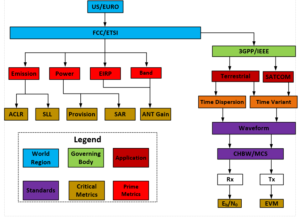
The missing component of the above diagram is competitive landscape and new technologies’ capability, feasibility, and their applications into new products for cost reduction and performance enhancement.
At ORTENGA, we take into account both the competitive landscape as well as introducing new technology with calculated risks.
Partner with ORTENGA to decompose your new product goals into HW/FW/SW requirements for cross functional engineering teams within your organization.
Inquiry send to: info@ortenga.net
Posted on March 27, 2019
Automotive Hidden Antenna
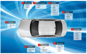
Fig.1 Tomorrow’s autonomous car with various communication gadgets.
Autonomous driving is the current emerging trend that is disrupting the traditional transportation market philosophy. Among all manufacturer, USA is leading in the development of autonomous vehicles followed by Europe and Asia. Electric (EV) or hybrid vehicle is the part of the autonomous vehicle, which most of the car manufacturer are dreaming to manufacture throughout the world. In addition to that, they are also interested in a cost-effective and fuel-efficient vehicle with attractive styling including the latest communication gadgets. All these ideas lead to lightweight design, sleek and reduced aerodynamics features. This market preference and technological advances have significant contribution in driving the development of automotive antennas. Today’s production vehicle is fitted with numerous antenna systems for different services; AM/FM radio, satellite radio, cellular band (4G: 690MHz—5 GHz); digital audio broadcasting (DAB: 200 MHz); remote keyless entry (433 MHz); tire pressure monitoring system (TPMS), GPS (1.1—1.9 GHz); collision safety radar (77 GHz) etc. as shown in Fig.1, and the gain/polarization requirement matrices in Table 1. With the 5G system, the low band frequency of the LTE band has been reduced to 617 MHz. It is well known that the antenna is the key element in achieving greater performance matrices in all communication system. A full feature vehicle will have more than 15 antennas installed on board. With all these antenna elements in operation, the space available for each antenna element is getting shorter and shorter. Today there are greater challenges in the design and development of automotive antenna system compare to previous generations vehicles.
Table 1: Gain and polarization requirement for different applications.
| Freq Band | Gain/CLAG:
(Composite Linear average gain) |
Polarizations: |
| FM:
76—90 MHz(JP) 88—108 MHz (US) DAB: 168—240 MHz |
(passive CLAG)
> -21 dBd > -10 dBd > -15 dBd |
H/V |
| DAB: 168—240 MHz | > -15 dBd | H/V |
| SDARS: | CP | |
| LTE:
LB;MB;HB |
> -7— -13dBi (CLAG) | H/V |
| GNSS/GPS:
L1/L2/L5 band |
> -3.0 — 3.5 dBi (LAG) | CP |
| WiFi Antenna:
2.4 GHz 5.5 GHz |
-10 dBi (LAG) | H/V |
| Radar cruise:
76-81 GHz |
Gain: 10-30 dBi
(depending on applications) |
H/V |
Partner with ORTENGA for design and development of your auto antenna product.
Inquiry send to: info@ortenga.net
Posted on March 25, 2019
What is Interleaving and Why it is used?
Interleaving is the process of placing/shuffling bits within a symbol in such a way that decrease the chance of “Burst Errors” due to fading.
There are two class of interleaving, Block and Convolutional.
Block interleaving is when the symbol is written into row of a matrix and transmitted along the column of that matrix.
Pseudorandom Block interleaving is subclass and when the symbol is written into row of a matrix and transmitted in the pseudorandom mechanism.
Convolutional interleaving is when the symbol is multiplexed in and out of fixed number of shift registers.
Partner with ORTENGA to design and develop your new product.
Inquiry send to: info@ortenga.net
Posted on March 21, 2019
Rayleigh vs. Rician Fading
Terrestrial Radio Link analysis consists of Line of Sight, Large Scale fading, Small Scale fading depending on the frequency, and Atmospheric Loss.
Large Scale Fading
Large scale fading refers to environment where the radio signal bounces of objects that are “much larger” than operating wavelength.
Large Scale fading is deterministic and it’s part of the Radio Link Budget Analysis.
Small Scale Fading
Small scale fading refers to fading environment where the radio signal bounces of objects that are “smaller” than operating wavelength.
Small Scale fading is random in nature, yet it can be introduced in the Radio Link Budget via Fade Margin. The fade margin represents the level of robustness for the Radio Link.
Small scale fading is typically modeled either by Rayleigh or Rician probability distribution function profile.
The radio signal is modulated by fading profile.
Rayleigh model reflects a channel with many multipath between transmitter and receiver which occurs in many Terrestrial radio applications, such as Cellular, i.e. 4G/5G, and WiFi, i.e. 802.11.
The probability distribution function describes the probability of occurrence as a function of radio signal envelope. The larger number of multipath between the transmitter and the receiver, the more spread the envelope radio signal envelope profile.
Rician model reflects a channel with one dominant, aka specular, path between the transmitter and the receiver. Obviously, the radio signal envelope for dominant path occurs with higher or distinct probability with respect to other multipath.
Rician model approaches Rayleigh probability density function as the dominant path becomes less and less in reflecting signal strength, therefore less pronounced.
In the case of 5G and WiFi applications, appropriate large and small scale fading terms must be included in the Radio Link Budget for robust radio design.
Partner with ORTENGA to analyze the Link Budget for your radio application and down select vendor/component for the design of new project.
Inquiry send to: info@ortenga.net
Posted on March 19, 2019
WiGig 802.11ad Data Rate vs. Range
The following graph illustrates Data Rate vs. Range for 802.11ad, aka WiGig, for OFDM signaling and Line of Sight, LOS, for mmW back haul applications. The mmW back haul can be realized with HGBF architecture.
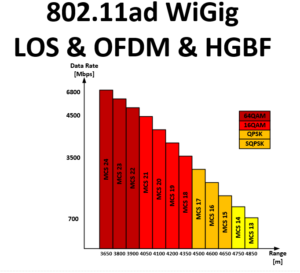
It takes into account the Atmospheric and path loss.
The system can be realized with Holograhpic Beamforming Architecture, HGBF.
ORTENGA can model and compute the impact of Large and Small Scale fading as well.
In addition, similar modeling is available for mmW 5G Waveform and applications.
Inquiry send to: info@ortenga.net
Posted on March 11, 2019
WiGig, 802.11ad Packet Format
The following diagram illustrates 802.11ad Packet Format.
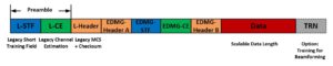
Preamble
Short Training Field, is STF used for receiver Automatic Gain Control, AGC, and synchronization, Automatic Frequency Control, AFC, whereas, Channel Estimation, CE is used for receiver assessment and adjustment of parametric depending on the channel behavior. Overall that is the purpose of “Preamble”, STF and CE.
Header
The Header is different for various PHY. It contains Modulation Coding Scheme, MCS, and the length of data, aka Checksum.
Data
Data is function of modulation and coding, MCS, and the length can vary depending on the PHY.
TRN
This an optional field meant for beamforming. It allows the beamforming algorithm to be trained and optimized via the User Equipment, UE, and/or Customer Premise Equipment, CPE.
Partner with ORTENGA to design and develop your new WiGig/802.11ad product.
Inquiry send to: info@ortenga.net
Posted on March 8, 2019
MIMO OFDM Systems Architecture
MIMO and OFDM are two essential technologies for many radio systems communication new applications, such as 5G and WiGig/802.11ad.
The following diagram illustrates MIMO OFDM Systems Architecture for Tx and Rx, bits to bits.
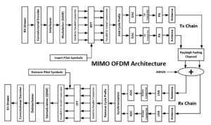
The number of antennas can be scaled up to meet desired performance, power, size, weight, and cost requirements.
Partner with ORTENGA for design and development of your new wireless product from concept to production.
Inquiry send to: info@ortenga.net
Posted on March 4, 2019
LEO Down Link
According to FCC regulations for Satellite EIRP, PFD on Earth, and analyzing, LEO Ku band User Terminal, UT, DL can have better than 10dB Eb/N0. By adding 8dB Turbo coding gain, that is ~18dB, conservatively. In other words, UT DL link can operate up to 256QAM Modulation and Coding Scheme, MCS, with existing MODEM SoC in the market.
The frequency reuse could be eight 250 MHz DL Channels for users in Ku Band, 10.7 – 12.7 GHz. Therefore the antenna requires 2 GHz bandwidth, albeit it could be dynamically tunable. Each of these 250 MHz channel is divided into multi access depending on the BW allocated by the network for each user. The user band selection occurs in the digital domain via MODEM SoC time slot partition. That is each UT process the 250 MHz band through RFFE and in the MODEM the data parsing and dedicated user data is selected.
Partner ORTENGA in designing and developing of your LEO SATCOM User Terminal. ORTENGA will work with you to define Throughput/Availability of Network Resources, Assignment of Resources to each Customer, Coordination of Spectrum with regulatory organizations, FCC and ETSI, and other users of the spectrum, Optimization of Link budgets and System Trade-Offs. ORTENGA will down select components such as SoC MODEM and Transceiver RFIC and required filtering which account for Thermal, Phase, I/Q imbalance, Nonlinearity, and Quantization noise, and Top Level Architectural documents for the Wireless System, AGC Algorithm and Gain Line up.
Water Fall Curves for BPSK, QPSK, 16, 64, 256, 1024, and 4096 QAM
Water fall curves represent BER vs. Eb/N0.
Eb/N0 is used so that BER is independent of BW and data rate.
N0 represents Additive White Gaussian Noise, AWGN density.
The following diagram illustrates BPSK, QPSK, QAM 16, 64, 256, 1024, and 4096 BER.
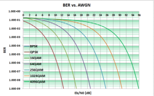
Observations
- BER is function of minimum Euclidean distance between constellation points. That is why QPSK and BPSK are performing the same.
- In the above chart, within the steep section of BER curve, small changes in Eb/N0 yields large changes in BER, hence “Water Fall Curves”. Consequently for achieving BER performance, adequate margin needs to be considered in the design of the system.
- Forward Error Correction, FEC, can be utilized to improve BER in expense of spectral efficiency. In other words, the FEC shift each curve to the left.
- In practice, there could be irreducible error noise floor due to fading where exponential becomes linear decay in the above chart. In other words, no matter how much Eb/N0 is improved the error remains constant above certain level when there is fading channel.
Partner with ORTENGA to analyze and design bits to bits from transmitter to receiver line up, down select appropriate MODEM SoC and Transceiver RFIC, switches, filtering, etc. components for your new product design and development.
Inquiry send to: info@ortenga.net
Posted on March 3, 2019
Which should be used, SNR or Eb/N0?
SNR stands for Signal to Noise Ratio and typically is figure of merit for signal quality in the RF domain.
Whereas, Eb/N0 stands for bit Energy to noise density ratio and typically is figure of merit for digital domain.
Radio System Engineers deal with SNR for quantifying signal quality in the analog/RF domain and the instrumentation is made to capture that. Radio Systems Engineers, however, aware that the SNR changes as the signal propagates through the system and is not necessarily a constant at each node. This is an important distinction which can be misleading, if not fully understood. If you plan to purchase a component, then it is imperative to understand this fact and how to use datasheet numbers for your systems, otherwise you would run into shortcoming issues at the systems level.
Digital System Engineers prefer Eb/N0 because it is independent of data rate as well as signal bandwidth, yet function of Modulation and Coding Scheme, aka MCS or MODCOD.
This metric, Eb/N0, is of prime interest at the input of the detector for obvious reason and stated in various standard documents without explicitly mentioning the reference plane. It should be transposed back to SNR when referred to receiver input port for the link budget and/or system line up model.
There are some related metrics such as Es/N0, BLER, FER, PER etc. Es/N0 stands for Symbol Energy to noise density ratio. BLER refers to Block Error Rate and it is the same thing as Frame Error Rate or Packet Error Rate. BLER, FER, or PER are metrics of L3 or Packet Layer, whereas Eb/N0 is PHY metric, L1.
Partner with ORTENGA for analyzing vendors’ datasheet and down selecting them for successful product design and development.
Inquiry send to: info@ortenga.net
Posted on March 1, 2019
802.11ad EIRP and Transmit Power
FCC dictates EIRP (or max Tx power), frequency band, and out of band unwanted emission for North America.
The following diagram illustrates FCC requirements for EIRP and Maximum Transmit Power for 57-71 GHz Unlicensed Band, also known as WiGig .
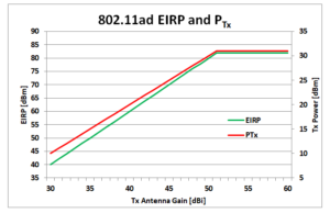
Observe that the EIRP and Transmit power is function of Transmit antenna gain. It is clear that as the transmit antenna gain is increased the EIRP allocated can increase, therefore allowing for longer range in the case of pencil beam radiation pattern.
Partner with ORTENGAto capture the radio communication systems requirements and constraints, design and develop feasible architecture, down select components from multiple vendor options, design and bring up the required HW, and validate the design of your new product.
Inquiry send to: info@ortenga.net
Posted on February 25, 2019
5G Infrastructure and 802.11ad Access Point Opportunities for Holographic Beamforming, HGBF, mmW Architecture
Both ABF and DBF 5G mmW infrastructure and 802.11ad Access Point architectures suffer from scaling for large antenna arrays.
ABF although less expensive than DBF, requires analog domain characterization and calibration over frequency, temperature, power level, prior to operation.
DBF although does not need extensive calibration requires redundancy of dedicated baseband and radio transceiver components with additional power consumption and BOM/cost.
Holographic beamforming, HGBF, offers cost effective compromise between ABF and DBF. The following architecture can be scaled to higher number of antenna elements which is function of the number of data streams as well as required gain.
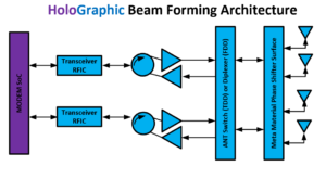
The MODEM SoC provides multiple data streams, each data stream dedicated for single user, UE.
Metamaterial phase shifter could consists of Diodes, MEMS, or LCD, see related Blog below for comparison.
Partner with ORTENGA to down select the appropriate architecture of choice, MODEM SoC and Transceiver RFIC, and required components, design HW, bring up the system, and validate the design for your new product.
Inquiry send to: info@ortenga.net
Posted on February 23, 2019
Open Source Interconnections, OSI, Layers
System level understanding of OSI layers is important for any architect who designs communication system. The following table summarizes PHY up to APP layers.
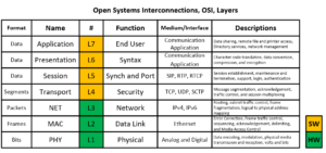
It should be noted in practice, RF Systems, Communication Systems, Network, and Application Engineers own all 7 layers.
Partner with ORTENGA to design and develop your new communication systems.
Inquiry send to: info@ortenga.net
Posted on February 21, 2019
4G vs. 5G Waveform Characteristics
3GPP release 16 to be published later this year with complete 5G systems information. In spite of that, the following table summarizes some of the key Waveform parameters for comparison with 4G.
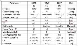
5G covers sub 6GHz as well as mmW, therefore some of the metrics such as; Subcarrier spacing, CP, Symbol duration, slot length, and overheads will be scalable based on the availability of network and operating frequency.
Observations
CP will be smaller to increase spectral efficiency compare to 4G, in particular in mmW. CP also helps in channel estimation of known signal.
Subcarrier, SC, spacing will be larger to mitigate Doppler shift due to time variant fading channel.
Both CP and SC will be scalable.
ORTENGA provides link budget analysis, transceiver line up behavioral model and/or simulation. MODEM interface definitions and algorithms.
Partner with ORTENGA for design and development of your new product.
Inquiry send to: info@ortenga.net
Posted on February 20, 2019
Fading Manifestations and Mitigation Techniques
The phenomenon of fluctuating signals at the receiver is called Fading. In practice, the signal fluctuation or fading could be up to 30dB. The fading is function of frequency, environment or channel, symbol rate, etc.
The following diagram illustrates fading manifestations to large and small scales. Large scale fading occurs due to Non-Line Of Sight, NLOS, reflection of signal off objects much larger than wavelength. Whereas, small scale fading occurs by objects which are in order of wavelength or smaller.
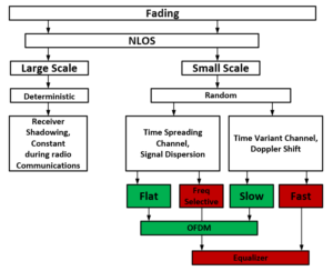
OFDM addresses Flat and Slow fading by radio architecture and waveform metrics. Fast and frequency selective fading are addressed by receiver equalizer.
Partner with ORTENGA to design and develop your new product.
Inquiry send to: info@ortenga.net
Posted on February 17, 2019
Antenna Tuners
Historically antenna tuners meant any passive interface impedance matching device between the antenna and the RF front end. This terminology has carried over to UE and/or mobile devices. In addition, as the need for multiple bands antenna increased, the need for antennas that can operate at multiple bands became prime interest of ODMs. Nowadays, antenna tuning could either imply antenna impedance tuning or antenna aperture tuning. The aperture tuning mechanism is part of antenna structure and changes antenna resonance frequency, hence operating at multiple bands.
Partner with ORTENGA to design and develop Antenna Tuning Algorithms for your new product.
Inquiry send to: info@ortenga.net
Posted on February 15, 2019
5G Use Cases Decomposed to Communications Platform
5G next generation Wireless Communications Standards is shaping to 3 distinct use cases, namely;
mMTC = massive Machine Type Communications
uRLLC = ultra Reliable Low Latency Communications
eMBB = enhanced Mobile BroadBand
mMTC is Very Low Throughput, VLT, communications between machines and data centers which collect and analyze data for either consumers and/or enterprises. This is the definition of NB-IoT, Narrow Band Internet of Things.
uRLLC is connecting mission critical end points. This could be communications between medical operating table and remote surgeon.
eMBB is Very High Throughput, VHT, mobile applications, what is known today as UE.
Each of the above use cases has specific applications and distinct target, therefore would require different HW/FW/SW to operate in its environment. In other words, decomposing the Application Layer down to distinct NET, MAC, PHY layers.
The following diagram illustrates the high level decomposition of the above 5G use cases.
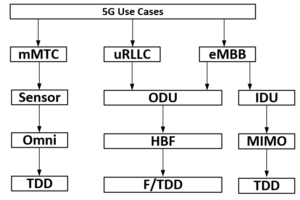
Partner with ORTENGA to design and develop your new product.
Inquiry send to: info@ortenga.net
Posted on February 14, 2019
5G Beamforming Architectures
The BeamForming architectures can be categorized into ABF, DBF, and HBF.
Analog Beamforming, ABF, controls the required phase shift in the RF front end in analog domain. Due to the nature of analog components and variations of part to part over frequency and temperature, each device has to be calibrated before operation.
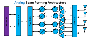
Digital Beamforming, DBF, controls the required phase shift in the digital domain at BBU/MODEM. Due to nature of digital process tight control, the calibration requirement is relaxed significantly if not all. However, the price for that is multiple transceiver units, therefore, additional power consumption.
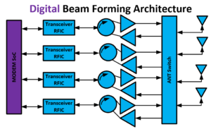
Hybrid Beamforming, HBF, controls the required phase shift in both Analog and Digital domains. Analog and Digital are used for coarse and fine tuning, respectively. The HBF is typically chosen for large arrays in order to optimize Calibration vs. BOM and Power consumption. This is the architecture of choice when scaling for large array is required.
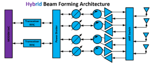
Partner with ORTENGA for Design and Development of your new product.
ORTENGA services will include but not limited to analyze trade-offs for new product architecture, line up and behavior model, down select ASIC or budgeting blocks within the ICs (in case you are semiconductor business), define interfaces, analyze self-interfering, filtering, intermodulation, phase noise, thermal noise, quantization noise, I/Q imbalance, headroom, dynamic range, frequency planning, and/or validating the design.
Inquiry send to: info@ortenga.net
Posted on February 8, 2019
5G Beam Forming Options, Diodes, LCD, MEMS Comparison
In order to achieve very high throughput, VHT, high SINR for high M-ary QAM has to be achieved. That implies actively beamforming connectivity between transmitter and receiver. Beamforming is a product of antenna array design, where inter element phase shifting occur during the operation.
Ferrite phase shifters have been used in legacy Phased Array Antennas for military applications and are very expensive. Commercial market has been using Diodes, MEMS and LCD for 5G beamforming. The following table summarizes the comparison between these options.
Diodes, LCD, MEMS 5G BF Comparison
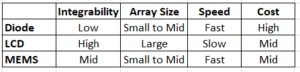
The comparison above table is based on the current technology and there are innovative techniques that can overcome some of the shortcoming depending on appropriate trade-offs.
Partner with ORTENGA to design and develop your new product.
Inquiry send to: info@ortenga.net
Posted on February 6, 2019
Plan for Success
Are you designing and developing a new product for future wireless market? If so, do you have to anticipate what the market look like in couple of years?
You are not alone in this journey and anyone with this challenge has to make some calls now and wait to see it bears fruit.
Unless you are part of big corporation with returning customers with specific request which allows you to design those feasible requirements into the new product roadmap, you have some blind views which would impact your new product.
Many new products do not make it to volume productions or global market with target ROI just because of over or under specifications.
Partner with ORTENGA to research market roadmap with Systems Engineering know how to define a marketable and cost effective product.
Inquiry send to: info@ortenga.net
Posted on January 7, 2019
What are the Criteria for Startups to be acquired by a Bigger Company?
In high tech industry, every year many small startups companies are being acquired by bigger and profitable organizations. What triggers these big companies to acquire Startups can typically be summarized in 3 major criteria.
Technology
First the startup has to have a new technology which would have use cases in the market space and uniquely positioned to surpass any other competitor that may exist.
Timeline
The new technology should bear fruit by less than 2 years. This timeline includes from acquisition to final product in the hands of end users and customers.
Cost
The new technology development should increase the bigger company bottom line with healthy margin and be synergic by complementing big company products portfolio.
In practice, many of the big companies have already invested into the startups prior to acquisition and know them inside out. The big company knows the issues/challenges and already have concrete plan in addressing them while acquired.
Startup Valuation
Obviously for this acquisition to be successful and smooth transition, the founders of startups must be on board. Every startup has venture capitalist that owns a significant portion of the organization, both people on top and new Intellectual Properties, IP. The investor has to be satisfied with the return of their investments plus expected profit while they know by prolonging the transaction would not bring them any more value on their investments. The biggest assets of any Startup are its IP. The IP consists of existing and incoming patents and most importantly the engineering that designed and developed the new product.
The preparation prior to acquisition could take between 3 to 6 months.
Partner with ORTENGA for your product design and development.
Inquiry send to: info@ortenga.net
Posted on January 5, 2019
Product Over and/or Under Specifications
Do you have a new product that does not sale as it was anticipated?
If so, you are facing an issue which many companies especially startups has. The new product is either Under Specified for features and metrics that the market needs, or if it costs more than what market wants to pay, it is Over Specified for some other parameters.
In case of many startups with a new product, they can both miss the required feature sets as well as over specifying some parameters such that the unit cost is much more than what the market is willing to pay. Therefore, they are facing with the product that does not sell and even with marked down prices and/or discounts, the product can’t be sold with any margin, therefore it is bottom line loss and drives the product to extinction.
You can always fix a design issue with another revision, however product mis-definition cannot be fixed with another revision.
Product definition is the most important part of any new product, especially for new technology and/or market. It requires system engineering with business acumen to research and define marketable feature sets with specific use cases and cost target in mind.
Partner with ORTENGA in your new product design and development.
Inquiry send to: info@ortenga.net
Posted on January 2, 2019