- Technical Requirements Pitfall
- The Impacts of Semiconductor on 6G
- New Product Introduction Window of Opportunity
- Evolution of Wireless Communication with Advance of Antenna Technology and Beyond
- LEO User Terminal Business Opportunities
- Return of Investment vs. Number of Competitors
- OneWeb and SpaceX User Terminal Limitations
- What is deciBell, dB, and why is it so popular in Engineering Communities across industries?
- 5G Collaborations
- LEO UT Pointing Angles Algorithm
- COVID19 is Challenging High Tech Industry
- Mobile Wireless Connectivity for Automotive Applications
- LEO vs. GEO UT Requirements
- What are Pilot Test Chips and Pizza Masks?
- Beamforming Algorithm for gNB, LEO, and WiGig
- Coronavirus Containment via Wireless Technology
- FR2 mmW Patch Antenna Design
- Most Effective Problem Solving Technique
- 16×16 Antenna Array Radiation Pattern with Beam Forming and SLL Management Algorithms
- LEO SATCOM and 3G/4G/5G Terrestrial Mobile Systems Architecture User Terminal
- Antenna Array Factor over Ground Plane
- Power Amplifier Efficiency Misconception, Under Utilization
- DAC Dynamic Range and Resolution for SLL Management Algorithm for 5G NR, LEO and Radar
- 5G mmW Antenna Design
- Innovation Recipe – Top down Approach
- PLL Phase Noise Sources
- Search and Identifications Radar for Smart Train and Smart Helicopter Markets
- Radar Pulse Compression Techniques and Waveforms
- Phase Shifting Mechanism for Beamforming and Beam Steering Radio Front End Module
- MIMO Application in SATCOM
- SLL Management Algorithm Flow
- Cost Effective Sub 6 GHz gNB Infrastructure
- Very Small Aperture Terminal, VSAT
- Beam Tracking Algorithm Flow
- 5G, SATCOM, and Radar Filter Requirements
Technical Requirements Pitfall
Many companies gather technical requirements and in one shape or form document those requirements to be shared with the rest of organization so that engineering can go about working on them and delivering the product based on those requirements.
The requirements typically come from a recognized authority that is trusted within the organization.
Typically, the same person has other responsibilities which are more important to this organization as a stakeholder, e.g. Director, VP, or CTO. Therefore, they are also responsible for executing and delivering the same requirements to accomplishment.
What can go wrong and most often happens than not, they are some critical requirements which are make or break the new product, yet get missed. The missing requirements could be what the market and end users value significantly, so much that it will be a factor before decision making to buy.
These requirements are what differentiate successful product from range of other products that either don’t make it to market, or find not much attraction even if they do.
The missing requirements are typically require sophisticated and/or challenging design but not necessarily out of engineering reach. Requirements should be written regardless of whether it is feasible or not, then technical feasibility and assessment, negotiating between stakeholders and various parties before signing off.
Neglecting these requirements will be short lived and the organization as whole would suffer, as they won’t be able to sale and return of investments.
Inquiry: info@ortenga.net
Posted on August 7, 2020
The Impacts of Semiconductor on 6G
As 5G technology being rolled out for Sub 6 bands and planned for mmW for the next few years, FCC is considering and will be auctioning additional mmW for licensed and unlicensed bands. The higher frequency bands are new to consumer product industry with many challenges to be resolved within short few years. This in turn opens the door to many business and engineering opportunities to be harvested. The mmW bands 5G semiconductor devices and their design into a successful product faces significant challenges.
6G bands are expected to starts around 100 GHz and continue to Sub Terahertz. At 100 GHz, the free space wavelength is only 3mm, and goes down linearly. The wavelength also scales down based on the dielectric constant of semiconductor material, which yields feasibility of its integration in the Front End Module, FEM. Therefore, Hardware design will be challenging and it will be replaced by appropriate package design for not only active but also passive elements such filters and even antennas.
Antenna in Package, AiP, or Antenna in Semiconductor, AiS, will be the way into integrated intelligence in future. The FEM will be much smaller and could be integrated into the semiconductor design. The mmW integration devices at Sub Terahertz will increase the significant of semiconductor technologies into higher gear with many opportunities which only few fabs around world will have necessary skills and capabilities to manage Sub Terahertz devices.
Currently, there are many undefined and unknowns to be understood and resolved for mmW band devices within the next few years, for antenna, power amplifier, switch, and filter manufacturers to address. Only handful of the investors in this market will be able to capitalize on their investment when the time comes in ~2025, due to necessary mmW and Semiconductor know how skills set.
ORTENGA is a consulting firm which assists antenna, power amplifier, switch, filter, and semiconductor manufacturers to prepare product conceptualization, design and development of appropriate algorithms controlling the antenna and front end module, study use cases’ feasibility, and execute successful new products for mmW bands and beyond.
ORTENGA Subject Matter Experts have both mmW design and semiconductor industry experiences.
Inquiry: info@ortenga.net
Posted on June 27, 2020
New Product Introduction Window of Opportunity
Startup companies typically go beyond the realm of current trends and conceptualize outside of the box product, design and develop before market realize they need it. That additional vision comes with risk or reward and new responsibilities.
The success of this new product depends not only on vision but also in demonstrating the capabilities of it in appropriate platform.
If you have a new consumer electronic product whether it is RFIC, SoC, small cell gNB, or SATCOM UT, you spent at least few years to design and develop this product. Now that you expect to get reward for your innovating design, customers are not rushing to buy. There is couple of things that needs to happen before you can reap that reward.
First, you have to ensure the platform which the product is demonstrated on the same or very similar to what the end user experience, not necessarily your customers need it. This enables your customers to see the end user experience and ability to make appropriate decision.
Second, the demonstrations in front of the customers still do not create any business deal, then there is a gap between what the customers need and what is presented. It is necessary to understand the gap via feedback given, whether it is direct or indirect.
There is a window of opportunity between the time the product is ready for engineering sample or demonstrations until the product is being replaced by alternative either from competitors or market requirement changes. This window of opportunity is within 6 – 12 months for semiconductor devices and perhaps up to two years for end user product. This time should be used to address number 1, 2, or both issues mentioned above.
Augment ORTENGA in your design and development for customer engagement and demonstrations of your new product before window of opportunity elapsed.
Inquiry: info@ortenga.net
Posted on May 14, 2020
Evolution of Wireless Communication with Advance of Antenna Technology and Beyond
Wireless communication realized when Hertz designed an experiment to illustrate radio connectivity in 1886 and then Marconi transmitted and received Morse code via Monopole antenna over Atlantic in 1901.
In 1983, first generation, 1G handheld communication mobile device made a first call. There were 3 factors which enabled such handheld device. It was well known that antenna size is proportional to wavelength. So in order to have handheld device, the antenna therefore the wavelength has to be in similar size. The size reduction pushed the Radio Frequency, RF, near 1GHz range. Armstrong discovery about Super-heterodyne receiver was enabler of RF domain circuitry. The third factor which is also equally important was the advance of semiconductor technology to realize Super-heterodyne transceiver in Integrated Circuits, IC or better known as RFIC.
Also 1G was using analog modulation, AMPS.
On the other hand, 2G realized the first digitally modulated technology, GMSK, which was another step in the right direction. By now, I/Q baseband signaling were realized to enhance spectral efficiency, bps/Hz, and start utilizing Shannon theory of capacity or data throughput.
The 3G was equally significant discovery, which was based on Code Division Multiplexing Access, CDMA. CDMA enabled ~100x better spectral efficiency in comparison to 2G via Pseudo Noise, PN, and orthogonal coding between transmitter and intended receiver in presence of other transmitters. 3G was perhaps the major leap toward Shannon limit. Although CDMA was known to be better technology, it took almost 10 years for the wireless community acknowledges that in 1995 since Qualcomm first used it for commercial applications, which changed the wireless industry.
4G or better known as LTE, introduced OFDMA technology which allows higher bandwidth and spectral efficiency in multipath fading of mobile communications. Between 2G to 4G, the advancement was in waveform and baseband technology which was implementations of communication theory. Also, during these times, the advance of semiconductor technology, on chip Digital Signal Processing, DSP and Moor’s law enabled shrinking the size of handheld mobile radio. Obviously, smart phone such as iPhone demonstrated the usefulness and traction by the industry for such handheld devices, which fueled the investments.
Now we are at the stage that semiconductor technology has reached 7nm for DSP with billions of instructions per seconds and can do more in controlling the radio front end module, FEM, dynamically.
During the past 100 year and following 4 decades since 1G, the radiating device, Antenna, had Omni Directional radiation pattern. Omni directional antenna can talk and listen almost in all directions. Therefore, the sensing does not need to know about the location of transmitter or vice versa and effectively “Blind”. The blindness of antenna reduces the power in the intended direction, therefore sub optimum SNR at the receiver. Throughput is directly proportional to SNR via Shannon theory. What if we could point the transmit radiation directly toward intended receiver? That would increase the SNR of the receiver significantly, therefore another leap in spectral efficiency, welcome to beamforming technology, 5G and beyond. Beamforming enhances the link by 30 – 40 dB at receiver SNR. This additional SNR enables higher modulation m-array which in turns are directly proportional to spectral efficiency, bps/Hz. The SNR enhancement is budgeted between gNB and UE. Therefore, the antenna is not “blind” yet “directional” and aware of receiver location. The awareness is enabled with appropriate antenna elements and algorithms driving them. Therefore the Antenna System Module, ASM, is software defined. Software defined Antenna structures require more than Antenna engineering know how which is legacy technology, but also requires additional features and algorithms to work dynamically with the rest of the wireless systems.
Augment ORTENGA in your ASM definition, design and development for successful gNB, SATCOM UT, or Radar product.
Inquiry: info@ortenga.net
Posted on May 12, 2020
LEO User Terminal Business Opportunities
Low Earth Orbit Satellite Communication User Terminals, UT, are being designed and developed by many organizations as well as startup companies. In few short years, the demand for these LEO UTs will be significant. This is the growing sector of SATCOM markets for many years to come.
SpaceX and OneWeb have launched many LEO satellites already and plan to have and will continue to reach over 2000 satellites for phase 1. For every LEO satellites there would be between 100 – 1000 UTs. So taking a conservative estimate; there would 200000 UT at phase 1 of the LEO connectivity. Each UT could cost ~$2000 if it is stationary, FWA. That is $400M UT opportunity at phase 1.
Phase 2 of LEO UT would have mobile capabilities for Autonomous Automotive; namely ships, trains, cars, trucks, and plains. That is where the expected market opportunity would be at least 10 fold, $4B.
Augment ORTENGA in your design and development of LEO SATCOM product definitions to harvest this new market before it matures.
Inquiry: info@ortenga.net
Posted on April 24, 2020
Return of Investments vs. Number of Competitors
In high tech industry, there are frequent new products introductions to the market.
Some of these become world class product as soon as introduction, because they address several end users’ requirements that did not exist before. For example, iPhone, Thumb Drive Memory, and Tesla Model S Automobile, to name a few, became popular and surpass competitors even though there were many legacy products before them.
Once these products demonstrate their traction and reach into market, many other companies jump into the race to duplicate similar products and cash in on their success. What is not clear to these new comers that, what would be their ROI? once they get into that market.
It is no surprise that number One to market, gets the most bang for the buck invested. Number two which is not typically far behind, perhaps by 6 to 12 months; also get a share of pie, albeit not the same margin, and reduces the margin for the number One company.
After that, the remaining companies can only make slim thin margin at best, less than 5% if any. Many of them realize that too late and drop of the market with significant loss of ROI and resources. The few companies which actually survive, you cannot expect any engineering support post sales for their products, and many does not even support pre-sales engineering support.
What sets apart the number One from the rests; the number One company has a unique product definition which was out of box, visionary and predicted the market before anyone else did. Reacting to market in new product development is not winner and almost guaranteed loss of ROI in the high tech industry.
Augment in defining your new product before developments.
Inquiry: info@ortenga.net
Posted on April 14, 2020
OneWeb and SpaceX’s LEO User Terminals Limitations
OneWeb and SpaceX have designed and are in the prototype phase of their LEO User Terminals.
While OneWeb relies on Mechanically Steered Antenna Array, SpaceX utilizes Phased Antenna Array technology.
In order to connect to first LEO satellite and handover to the second incoming LEO satellite, there is a tight time constraint, which Mechanically Steered Antenna Array solution requires two antennas. These antennas are typically dish antennas with high profile. This high profile limits these LEO UTs to Fixed Wireless Access, FWA, applications and market.
The Phased Array Antennas however are suitable for fast switching speed via single antenna array and can connect to LEO satellite 1 and handover to satellite 2, dynamically in order of ~100 us time, which are feasible for LEO requirements. However, Phased Array Antennas are expensive and typically used for military applications and cannot be streamed line for commercial applications.
There is a greater opportunity for Mobile LEO UT which neither of the above solutions address form technical and cost perspective. There is market for flat antenna array design in Ku and Ka bands. Flat Antenna Array is not only attractive for commercial applications but also addresses mobile LEO UT, such as Autonomous Automotive.
It is view of ORTENGA that cost effective Flat Antenna Array can be realized to address mobile market whether it is LEO or 3GPP Release 17 networks.
Augment ORTENGA with your design and development teams to address growing Autonomous Automotive markets.
Inquiry: info@ortenga.net
Posted on April 8, 2020
What is deciBell, dB, and why is it so popular in Engineering Communities across Industries?
The deciBell, dB, is named after Alexander Graham Bell who worked at American Telephone and Telegraph Company, widely known as AT&T nowadays.
dB is simply defined as 10*log10 (Power ratio).
Various industries are using dB as the unit of measure to quantify key Parameter Indicators, KPI.
You can see it used in Audio industry to quantify the strength or power of speaker loudness. You can find that to be used in Electrical, Communication, Radio, and Radar industries.
There two reasons behind ubiquitous acceptance of dB.
First, dB simplifies mathematical computation, multiplications and divisions become additions and subtractions in logarithm, respectively. In other words, you don’t have to multiply or divide anymore, just add or subtract numbers in any scientific equation.
Second, dB magnifies/compresses very small/very large quantities, respectively, such that these quantities become tangible to human senses. In other words, you don’t have to deal with very small or large number, just dealing with numbers between 0 to +/- ~100 dB that are better understood by anyone.
For instance, a healthy ear can hear between 0 to 120 dB Pressure Sound Level, PSL. In other words, 0dB PSL is bare minimum human ear sensitivity and 120 dB PSL though painful but maximum tolerable sound level. 0dB reference stands for 20 uPa pressure level. Another way put, healthy ear can hear anywhere between 20 micro Pascal as minimum to 20 Pascal as maximum signal levels.
Your mobile phone’s receiver has about ~100 dB dynamic range.
Conversions of going from Power ratio to dB and vice versa are fairly easy, once you memorize dB values for ratio of 1 to 10.
Then, effectively you can compute dB for any ratio; therefore, any equation can be done on the back of envelope without calculator or computer.
Inquiry: info@ortenga.net
Posted on April 5, 2020
5G Collaborations
Many leading startups which successfully design a product for 5G market are realizing that in order to promote and demonstrate their own product, they must collaborate with at least one or two other 5G startups to convincingly illustrates the functionality, parametrically, and usefulness of their product.
The following figure illustrates typical 5G blocks which could be part of FWA, gNB, CPE, UE, IoT, etc.
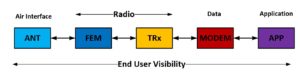
There are only handful companies which have R&D capabilities that can spend resources for all of the above 5G components before their customers and demonstrate the end user metrics.
Any startup that only design and develop one or even two components of the above figure, have to choose partner and collaborate to successfully demonstrate their product.
Selection of appropriate 5G components will be critical in succeeding not only for functionality of your product but also to show the optimum performance metrics. It is simple to recognize the required initiative that additional systems analysis must be done before your customers give any feedback about your product. This initiative is well spent resources and critical to your product successful launch and traction by end users.
Augment ORTENGA to identify and design in appropriate components which interface with your product before demonstrating in front of your customers.
Inquiry: info@ortenga.net
Posted on April 1, 2020
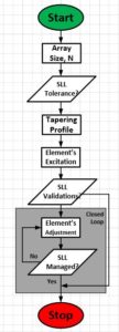
LEO UT Pointing Angles Algorithm
The following flow diagram illustrates LEO UT Pointing Angles Algorithm.
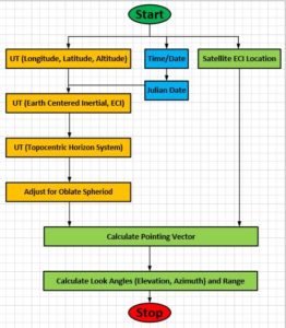
Obviously, additional Tracking Algorithm will be utilized due to LEO satellites’ handover.
Augment ORTENGA in your design and development of Antenna System Module, ASM, and algorithms development for LEO UT or gNB.
Inquiry: info@ortenga.net
Posted on March 31, 2020
COVID19 is Challenging High Tech Industry’s Operation
COVID19 forces social distancing for the sake of public health.
Big corporations and small business startups are trying to stay afloat by figuring out how to operate without being in the office.
Productivity should be measured by deliverable.
There is simple rule that everyone in the industry agrees and follows regarding information sharing, “need to know basis”. It implies that you can only share information within your company when there is need for collaboration; otherwise it is not shared even with your coworkers.
A similar rule is being developed that would change many things in our standard of operation and working habits, “need to be in office” sharing. That implies to preserve productivity due to any unforeseen issue in future that can abruptly interrupt working in the office; proactive companies are planning to adapt rules that would allow employees to Work From Home, WFH, so long as their duties can be fulfilled. The implication would be; office presence is only required, if needed to accomplish your work, otherwise WFH.
Another underlying implication is that more companies will open up to contract and/or consulting workforce services, as they are also working remotely without day to day presence, and save cost due to office spaces, payroll taxes, benefits, and paid only for deliverable.
Companies which recognize these new realities, they exploit and cash in on this day and age of high tech industry via 5G, online connectivity, remote collaboration and execution.
Inquiry: info@ortenga.net
Posted on March 30, 2020
Mobile Wireless Connectivity for Automotive Applications
Automotive Connectivity will be growing within the next few years in high end and luxury Automobiles and matures as must have feature by 2030. There are two platforms which will provide the wireless connectivity, LEO SATCOM and 5G Terrestrial networks.
Size, Weight, and Power consumption, Temperature tolerance, SWaPT, will be making or breaking thresholds for any LEO User Terminal market acceptance by automotive manufacturers. Later on, Cost will join the C-SWaPT as another metric for the industry.
The 16×16 antenna array will be ~30cm x 30cm, ~5cm thick including ASM, FEM, TRx, MODEM, and APQ for Ku band. Therefore, it will fit in any automobile. The power consumption can be tailored for automobile applications supplies with range of ~1 – 20 W depending on Rx, Tx, or sleep modes. Average transmit mode power consumption is ~15W. Temperature tolerance will be handled with meticulous Thermo-Safe design.
Regarding 5G mmW band, this design will be housed in even smaller volume of ~10cm x 10cm x ~3cm including all electronics necessary for Mobile User Equipment and power consumption ~10W.
It is worth mentioning that a combined LEO UT and 5G UE can be designed within ~40cm x 40cm to operate in both LEO and Terrestrial networks. The unit cost of such a terminal can be approximated to ~$5000.
Augment ORTENGA in your design and development team to tailor LEO UT and/or 5G UE/CPE/gNB/FWA product.
Inquiry: info@ortenga.net
Posted on March 25, 2020
Memoryless and Hysteresis Organizations [ps2id id = ‘Memoryless_Hysteresis_Org’/]
Memoryless electronic device is a device that does not remember its last states, therefore behaves the same regardless of increasing or decreasing in its dynamic range.
On the other hand, hysteresis device behaves and is dependent on its history of its last state.
Organizations have shown similar behaviors.
Some organizations are memoryless, that implies, they don’t promote people within the organization. They hire their leaders from outside of the organizations.
Other organizations nurture and organically develop their leaders internally. Their leaders have typically worked from low to higher ranks, until the individual shows the worth and impact within the organization before it becomes a leader within the organization.
There are advantages and disadvantages for each organization.
Memoryless organization bets on the new idea that can come from outside to resolve technical and non-technical challenges within the organization. They try new solutions to the existing challenges. Choosing appropriate person externally helps with innovation and adaptability of the organization.
Hysteresis organization relies on solving their problem with people who have worked within the organization and know its root cause and potential solutions. They feel someone from inside the organization can understand and solve their problem. Choosing appropriate person internally helps the continuity and illustrates respect to the existing organization in place.
Each approach has its own merits and disadvantages. Staying with one approach all the time, could cause issue especially with startups which has limited runway of funding. It would be wise for critical positions to select the best person in fulfilling it, regardless of internal or external.
Inquiry: info@ortenga.net
Posted on March 20, 2020
LEO vs. GEO UT Requirements
Low Earth Orbit, LEO UT has distinct differences which can make or break Geostationary Earth Orbit, GEO UT.
- LEO satellites are mobile relative to UT on earth, therefore, UT has to not only to point to the satellites but also track the satellite and then switch to another mobile satellite coming into range.
- LEO UT have only point +/- 45 from broadside, therefore there is better link connectivity no matter where the UT is on earth.
- LEO satellites are at fraction of distance relative to GEO satellites form earth, therefore the latency is fraction of GEO link, ~60ms, as well as fraction of EIRP, therefore less transmit power is required, for uplink or Reverse Link, RL.
Items 2 and 3 above appear less stringent requirements for LEO relative to GEO.
However, regarding item 3, G/T requirement is similar to GEO UT given required throughput, which is the most challenging implications of UT requirements. Regarding item 1, it has some subtle yet challenging implications which become new requirements. This one requirement can make or break legacy design, if LEO UT is not designed properly. The UT must find the LEO satellites in blink of an eye and track it for ~10 seconds before switching to another LEO satellite. This occurs over and over to keep the radio link without interruption. In addition, if UT is itself mobile, then the challenge of finding LEO satellite and switching to another every ~10 seconds becomes exponentially more difficult. That is where LEO UT needs robust beamforming, beam tracking, and SLL management algorithms that work dynamically on the fly. These algorithms work hand in hand with Antenna Module.
There is additional requirement for Bandwidth. LEO radio links are supposed to provide a better throughput. This additional throughput requirement is achieved by two system metrics. First a better C/N or Eb/N0 which yield better spectral efficiency is required. Second a wider operation bandwidth is required of the Antenna, Transceiver, and MODEM.
The above requirements are challenging and many engineering teams across the globe are trying to innovate commercial grade solutions.
It is worth to mention that LEO UT can significantly cost less than GEO counterpart for two reasons. The MODEM and FEM ASIC can be leveraged from cellular market, if properly architected, defined, and selected. GEO UT operates at order of magnitude higher transmit power and costs between 20 – 30 % overall UT, whereas LEO UT requires much lower power and smaller factor of FEM.
Augment ORTENGA into your design and development of LEO UT team for successful applications of requirements and their implementations.
Inquiry: info@ortenga.net
Posted on March 11, 2020
What are Pilot Test Chips and Pizza Masks?
Application Specific Integrated Circuits, aka ASIC, are high volume electronic circuits which provide functionality of some portion of communications and/or radar systems. One of major cost components of these ASIC, is semiconductor mask. Semiconductor masks are used for lithographically fabricating the semiconductor devices onto wafer. Each wafer requires multiple masks for various layers of fabrications and etching. A typical vanilla CMOS process could easily have 200 masks or more and they could easily cost as much ~$3M depending on the geometry and size of the gates.
Each all layer revisions of ASIC require all ~200 masks; therefore it becomes prohibitively expensive for smaller companies or even big corporations to tape out any design for single project/product.
In order to save cost for any trial of ASIC before design is finalized, it is customary to run some pilot test chips to validate the design as well as the process performances. For test chips run, it should only be enough number of them to be validated and characterized for desired performances, KPI.
Therefore, many semiconductor fabrications offer Pizza Mask, where number of companies can share the cost for the masks, ~$3M, and get only small portion of wafer area, “pizza”. Very large corporations typically have their own pizza masks for multiple internal projects, test chips. Or tandem with another project masks for couple hundred devices.
Each wafer lot is typically 25 wafers, and small portion of pizza/wafer, can produce few hundred devices per lot, enough to validate design topology and performance metrics.
Augment ORTENGA in your semiconductor device design and developments to utilize cost saving proven techniques which are not only benefits R&D cost, but also improves TTM, hence ROI.
Inquiry: info@ortenga.net
Posted on March 3, 2020
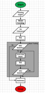
Beamforming Algorithms for gNB, LEO, and WiGig
Beamforming technology is utilized in gNB, aka 5G infrastructure, LEO SATCOM, and WiGig technologies in addition to radar applications.
Figure 1 illustrates the pointing algorithms for the above technologies. gNB and WiGig method of pairing Tx to Rx are similar, therefore the same pointing algorithms can be utilized. LEO SATCOM has different constraints which are show at high level in the above flow diagram.
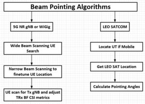
Figure 1: Beam Pointing Algorithms flow diagram for gNB, LEO, and WiGig Technologies
ORTENGA can support your product in implementing the Beamforming algorithm, whichever technology is needed.
Inquiry: info@ortenga.net
Posted on March 1, 2020
Coronavirus Containment via Wireless Technology
As news of Coronavirus spreading globally raises public concern, it seems prudent to proactively work toward containment and resolution to this contagious virus, until appropriate treatment is in place.
Wireless technology has enabled wireless connectivity in many high tech regions of the world. Many jobs/projects can be done remotely from home office, at least for part of the week, therefore minimizing the human contacts outside of home and potentially contracting and inadvertently spreading the disease during the containment periods.
Leading companies in the industry allow employees to complete their project, regardless of whether they are physically in the office or working from elsewhere.
Proactive companies are also preparing contingency plan to mitigate the work flow, should the virus becomes a wider issue.
Public health is in interest of everyone while remote and home office is becoming more acceptable among many companies regardless of any particular contagious health issue or not.
Work with your HR and project manager to plan for remote working and appropriate forum interfacing with your coworkers and colleagues while you are not physically at your company.
Once or twice a day online synchronization, Virtual Stand up meeting, with your team may suffice the project needs.
Public health requires Public awareness and contributions.
Inquiry: info@ortenga.net
Posted on February 27, 2020
FR2 5G mmW Patch Antenna Design
Figure 1 illustrates FR2 5G Patch Antenna design centered at 27.946 GHz.
Figure 1: E and H Plane Patch Antenna radiation pattern centered at 27.946 GHz
It is worth to mention that maximum Gain is 6.7dBi with 51 Ohms input impedance at FR2 5G center frequency, BW = 850MHz.
This design can even be optimized further for your application and/or requirements. In addition, it can be integrated to 16×16 Antenna Array to increase the gain up to 30dBi, if desired.
Consequently, ORTENGA Beamforming and SLL management algorithms can derive the antenna array to enhance the system performance in actual operation.
Augment ORTENGA in design and development of mmW Antenna design and validations for gNB, Radar, Autonomous Automotive, or WiGig.
Inquiry: info@ortenga.net
Posted on February 26, 2020
Most Effective Problem Solving Technique
High impact leaders and/or managers learn to identify an issue or problem as soon as there is a roadblock and needs resolution. These individuals may not have technical know-how, yet they are keen to work with others who do and exercise active listening technique with appropriate and open questions and answers sessions. Once the problem is identified, they are acknowledge it and make it known to the rest of the team and seek advice in resolving it.
Here are simple yet challenging four steps for resolving any technical issue;
- Interface and listen to appropriate stakeholders facing the issue
- Ask related question to convince yourself of the problem to a level you can explain to others
- Acknowledge the problem in front of your team
- Seek advice and resolution by involving your team
A problem cannot be solved if it is not acknowledged. Those who deeply understand the issue, have the key to resolution. After all, every solution is within the same problem, we just fail to see it at first.
Inquiry: info@ortenga.net
Posted on February 25, 2020
16×16 Antenna Array Radiation Pattern with Beam Forming and SLL Management Algorithms
Figure 1 diagram illustrates a 16×16 (64 Square Wavelengths) rectangular antenna array which is typically utilized in 5G infrastructure, gNB, 802.11ay, WiGig, Fixed Wireless Access, FWA, Short Range Radar, SRR, or eHealth nowadays at mmW frequencies. Keep in mind that this array can be integrated as part of mMIMO as well.
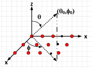 Figure 1: 16×16 Rectangular Antenna Array in x-y plane
This 256 elements array has considerable directivity and gain. The additional gain of array over single element antenna is 21 – 24 dB, which enables dB per dB better SINR in the radio link, consequently higher Spectral Efficiency, SE. It is worth mentioning that higher SINR or effectively Eb/N0 results in higher order modulation alphabets, [bps/Hz]. A higher order modulation alphabet is directly proportional to spectral efficiency with proportionality constant of Code Rate, i.e. SE = (bps/Hz) * CR. This is in essence the reason behind 5G NR throughput or better range/velocity resolution in radar applications.
Figure 2 diagram illustrates radiation pattern of the array when it is pointing to broadside or theta0 = 0°. For this configuration, the directivity and gain are at highest, whereas the beamwidth is narrowest.
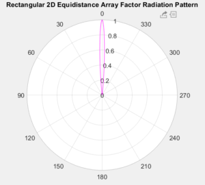
Figure 2: 16×16 Antenna Array Beamforming at Broadside, theta0 = 0°
Figure 3 illustrates 16×16 AF Universal radiation pattern for theta0 = 0°, where HPBW = ~7°.
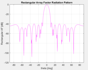
Figure 3: 16×16 AF radiation pattern Universal Plot for theta0 = 0°
Figure 4 diagram illustrates array pointing at theta0 = 45°.
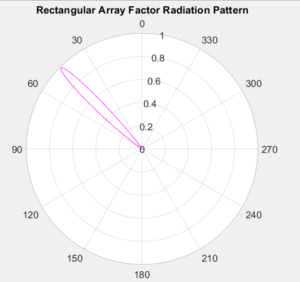
Figure 4: Antenna Array Beamforming at 45° from Broadside
Figure 5 illustrates Universal plot of the array at theta0 = 45°.
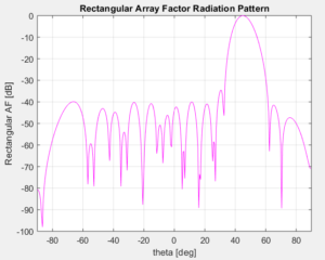
Figure 5: 16×16 AF Universal Plot at theta0 = 45°
Notice the HPBWtheta = 9° has increased, i.e. aka beam broadening, as the array pointing away from broadside. That in turns results in gain roll off ~2dB, which is expected due to decrease in array aperture size.
Figure 6 illustrates Universal plot of the array pointing at phi0 = 55° for theta0 = 45° plane or cut, HPBW = ~9°.
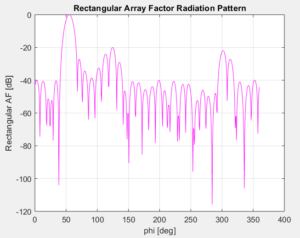
Figure 6: 16×16 AF radiation patter for theta0 = 45° plane
For the antenna array the SLL can be designed to not exceed specifications with minimum penalty in AF directivity or equivalently the gain. For this optimized design, the directivity trade-off is ~0.5dB, yet SLL are typically improved more than several dB at the least. Therefore, during the operation of overall radio system, the transmitter power efficiency is optimized and yields better overall C/N or SINR, consequently, better spectral efficiency is achieved.
Any other (theta,phi) pointing angle can similarly be synthesized by the 16×16 antenna array. The above figures are just examples of antenna array capabilities.
These radiation patterns are for isotropic sources and depending on your system impairments additional noise sources can be introduced in to simulations to mimic the system under analysis and synthesis. For instance, ORTENGA can include amplitude taper noise and/or inter-element phase error based on HW implementations and limitations, two common errors that contribute to KPI of any antenna array.
ORTENGA has modeling with noise profile for beamforming and SLL performance for various tapering profiles. Also, ORTENGA has capabilities to design larger array size, circular, and/or concentric shapes. ORTENGA algorithms provide minimum SLL for minimum beamwidth, effectively optimum antenna array gain. There is misconception that maximizing antenna array gain provides better C/N. However, in practice the overall transmitter must meet FCC emission regulation during the operation, which forces the transmitter to back off from maximum power due to unwanted SLL, therefore under-utilizing transmitter power efficiency.
Augment ORTENGA in your design and development of Antenna Array technology to assist you in developing appropriate models in determining performance behavior of your communication or radar systems.
If you are interested about ORTENGA licensing agreement for the above algorithms for your product, contact us.
Inquiry: info@ortenga.net
Posted on February 18, 2020
LEO SATCOM and 3G/4G/5G Terrestrial Mobile Systems Architecture User Terminal
The following architectural diagram illustrates user terminal which can support both LEO SATCOM as well 3G/4G/5G Terrestrial mobile communication systems.
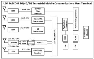
Observe that it relies on existing RFIC transceiver as well as MODEM SoC by ADI and Qualcomm, respectively. Obviously, the multiple antennas and antenna array as well as diplexer can be designed to support the user terminal. It worth mentioning that X55 SoC has beamforming and beam steering capabilities as well as primary and diversity channels with sensitive Eb/N0 which can also support higher QAM modulation with Adaptive Coding Modulation, ACM, feature set.
This architecture can be implemented and integrated into an actual product in about 1 year time frame.
Augment ORTENGA in your analysis, architect and systems definitions for LEO SATCOM and Terrestrial Mobile Communications Systems.
Inquiry: info@ortenga.net
Posted on February 11, 2020
Antenna Array Factor over Ground Plane
5G NR, gNB, LEO SATCOM, radar, and WiGig rely on beamforming, therefore Active Electronically Scanned Antenna Array, AESA. Typically AESA has ground plane, consequently image theory must be utilized to arrive at proper radiation pattern of AESA for simulation and therefore in actual applications. This particularly becomes important and critical for implementing Beamforming, Beam steering, and SLL management algorithms.
The appropriate simulations enable the architect, system design, and managements to validate assumptions made for feasibility of design. ORTENGA provides simulation tools to validate your design and goes beyond what appropriate Phase Array Tool Box or SystemVue provide, independently.
Augment ORTENGA into your architect and system design teams to validate design before its implementations.
Inquiry: info@ortenga.net
Posted on February 9, 2020
Power Amplifier Efficiency Misconception, Under Utilization
Many companies strive to design more efficient Power Amplifier, PA. In doing that, these companies utilize new technology and engineering resources over design and development cycle of project to achieve more efficient standalone Power Amplifier.
What is missing in overall goal is, analysis and addressing overall wireless systems operating power efficiency. Power Amplifier efficiency does not necessarily translate percent for percent to less power consumption by the transmitter, if there are other culprits in the transmitter architecture which prevent achieving more efficient transmitter.
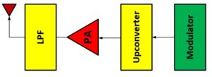
The above figure illustrates a typical wireless transmitter. Power Amplifier efficiency is one of the figure of merits. Except Power Added Efficiency, PAE, is defined at maximum power rating of the PA, which is rarely the actual operating point of the overall wireless system.
Particularly, many SATCOM UT operates 3-5 dB below rating of PA. The power added efficiency drastically reduced at couple of dB back off point of PA P1dB. Therefore, all the hard work put in the PA design goes under-utilized.
The following table illustrates under utilized power in Watts due to PA back off in order to meet EVM and distortion metrics.
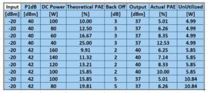
You will be better off designing an architecture which does not suffer during the actual dynamic operation of the transmitter and leave power on the table while the power amplifier is capable of delivering yet under utilized by the system.
Augment ORTENGA in your analysis, design and development team to architect transmitter in such a way that can benefit from PA efficiency and utilize every Watts or power in the system.
Inquiry: info@ortenga.net
Posted on February 8, 2020
DAC Dynamic Range and Resolution for SLL Management Algorithm for 5G NR, LEO and Radar
SLL management Algorithms relies on tapering the waveform or antenna array excitations. This is typically achieved with Digital to Analog Converter, DAC, in advance systems. The DAC dynamic range depends on maximum to minimum ratio of the excitations or waveform, which may or may not impact resolution depending on the topology of tapering.
In some cases, it may be sufficient to require DAC ENOB based on the dynamic range.
On the other hand, there are scenarios for optimum performances; the ENOB is driven by the actual resolutions and noise suppression requirements of tapering.
Augment ORTENGA in your Beamforming, Beam Steering, and SLL Management Algorithms to design appropriate HW as well as required algorithms.
Inquiry: info@ortenga.net
Posted on February 7, 2020
5G mmW Antenna Design
The high data rates required for the 5G standards leads to the need for greater bandwidths. This has moved the required operating frequency bands up into the millimeter wave range for the 5G communication systems.
The mmWave antenna design for 5G has the following important aspects: the beamforming and synthesizing antenna arrays, designing the antenna elements; designing the feeding network, the effect of the coupling between the adjacent antenna elements, the effect of surrounded materials on the radiation characteristics of the antennas and power consumption, and the thermal dissipation.
The beamform is designed in order to maximize each user’s received signal power while minimizing the interference signal power from the other users.
The antenna design for 5G mmWave communication systems include design antennas for smart phones, indoor small-cell networks, and the base stations.
The antenna design for the above problems focuses on design of ultrawideband (UWB), wide scanning, and dual-polarized phased arrays that shall scan the beam electronically. Examples of this design are arrays of patch antennas (Figure 1), planar dipoles, or bowtie antennas with two orthogonal feeding mechanisms to excite horizontal and vertical modes for each element. In addition matching networks should be designed to improve the impedance matching. The distances between the patches in the arrays design are λ/2 center to center which are 5 mm at 30 GHz and 3 mm at 50 GHz.
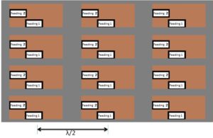
Figure 1: Example of planar patch array with orthogonal feedings (Feeding 1 and Feeding 2). Note that the boxes of “Feeding 1” and “Feeding 2” are just block diagrams that take different shapes and locations based on the design.
Implementing this design for the orthogonal modes is challenging because the difficulty of integrating the orthogonal feeds and the existence of resonance modes from the conductors surrounding the antennas.
Reconfigurable antenna design is used in order to switch between different 3D radiation patterns of the antenna and different polarization settings.
The reflection coefficient should be simulated when the antenna excited by the practical feeding structure over a wide frequency range covers e.g. the FR2: 24.25-52.6 GHz. The radiation pattern and the directivity level should be simulated and the stability of the radiation pattern should be tested over the operating frequency band and the symmetry in co-polar and cross-polar components should be inspected.
Over the air testing (OTA) requirements, such as the size of the chamber and the positioner choice, should be determined based on the size of the antenna structure and the radiation pattern characteristics. If the size or the position of antenna is unknown then we use white box dimensions which is a box include the electronic circuits with the antenna to determine the chamber size. In addition, we decide whether we use direct far field measurements or compact antenna test. In the direct far field measurements, the measurements of the field magnitude are performed in the far-field zone of the antenna while in the compact antenna test the measurements of the complex field are performed in the radiated near-field and then a near-field to far-field transform software is used.
Simulation of massive array of tightly coupled antennas with the feeding network over an UWB, e.g. the FR2: 24.25-52.6 GHz is challenging.
We can design the antenna arrays for the FR2 including the mutual coupling between the antennas, the feeding and impedance matching network, and analyze the effect of the surrounding metals and materials on the antenna performance.
We can solve such kind of problems and develop or choose which method and software is the best for your design.
Author: Hany A. Raouf, PhD
Inquiry: info@ortenga.net
Posted on February 6, 2020
Innovation Recipe – Top down Approach
Any innovation requires challenging the status quo.
Those, whom are satisfied with the existing solution(s), typically do not seek to enhance the solutions to a problem.
Many companies which are missing out innovating into their products on regular basis or brand new product with features and performances beyond existing market trends have something in common; their design approach flows Bottom up.
The questions to internal, external, and consultants are around low level blocks in the system and how to enhance it, say mixer in a radio. The fallacies in that question are that it is already assumed the next generation of radios will embed a mixer. Perhaps detrimental assumption is that people whom have an extensive background and experiences for that field are in better position to answer that question.
New ideas come from looking at a problem with a different angle which was missed before. It is more likely someone without prior knowledge and background that may come up with an innovative solution. Obviously, the new comer must understand the problem before attempting to solve it. That burden is on our shoulder to pose an appropriate question.
This is the story of an actress Hedy Lamarr and a composer George Antheil the inventors of Code Division Multiple Access, CDMA, which has enabled Qualcomm to surpass all of its competitors. While everyone around the globe was working on TDMA or FDMA, in 1985 Qualcomm determined that CDMA will provide ~100x more capacity relative to TDMA and FDMA. It took approximately 10 years to prove that to remaining industry and show CDMA can be implemented and utilized in cellular market.
It is much better problem solving approach if the system in hand is solved from Top down. First, gathering constraints and stating requirements for that radio by the product definer, then, attempting to find various architectures that may address those requirements.
Unfortunately, nowadays many companies big or small utilize Bottom up approach and miss opportunities to lead their own market.
ORTENGA engineers utilize Top down approach to solve our clients’ problems.
Inquiry: info@ortenga.net
Posted on January 31, 2020
PLL Phase Noise Sources
Phased Lock Loop, PLL, is a negative feedback frequency synthesizer of choice for Integrated Circuits, IC. There are four phase noise sources in any PLL, namely; Crystal Oscillator, XO, Phase Frequency Detector, PFD, Voltage Control Oscillator, VCO, and Divider.
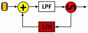
The analysis of output phase noise can be modeled in steady states as four independent sources for a linear system, shown in color in the above block diagram.
The Low Pass Filter, LPF, typically does not contribute to the PLL noise. XO is typically the lowest noise source in the PLL. For phase noise budget analysis at a system level in a typical design, XO, PFD, and Divider noise sources are lumped together and called PLL noise, whereas VCO noise is singled out independently. VCO phase noise profile is high pass, while PLL has low pass phase noise profile.
Augment ORTENGA with in your PLL design team for phase noise analysis and line up budget of any radio and design validation.
Inquiry: info@ortenga.net
Posted on January 29, 2020
Search and Identifications Radar for Smart Train and Smart Helicopter Markets
Radars are used in advanced airplanes as part of Altimeter as well as Search and Identify heading of an airplane using legacy technology.
Civilian Helicopters are typically lack radar due to cost of legacy radar.
Also Trains are rarely use radar for navigation.
With the advance of semiconductor radar System on Chip, SoC, which are designed for Autonomous Vehicle, AV, the cost of realizing such radars are lowered.
AV radar companies are uniformly focusing on Automotive market, which is a large portion of AV radar market, yet will return investment in several years, 2025 onward for large volumes and later for mass productions.
There is another untapped market, which is not necessarily being designed for, Smart Train and Smart Helicopter markets, STSH. STSH market can use these radars to navigate in high populations and cities to avoid accident and/or crashes as it becomes evident and painful to hear on too often occasions.
Rest in Peace Kobe Bryant.
Inquiry: info@ortenga.net
Posted on January 27, 2020
Radar Pulse Compression Techniques and Waveforms
It is well known that radar waveform can either be tailored for range or its resolution. In other words, the requirements for long range and fine range resolution are contradictory in nature. In addition, it is also true that range vs. velocity resolution have contradictory design constraints which cannot be met simultaneously, unless more sophisticated waveforms are utilized which are known as Pulse Compression Technique.
The following diagram illustrates various Analog and Digital Pulse Compression Waveforms which are utilized by Radar Waveform designers to optimize range and its resolutions.
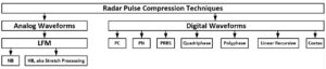
Pulse Compression and MIMO radar can be utilized to design appropriate waveform constraints for range, range resolution, and velocity resolution.
Augment ORTENGA with in your design team to deliver radar product for Autonomous Vehicle, eHealth, Smart Home, Smart City, or other applications.
Inquiry: info@ortenga.net
Posted on January 25, 2020
Phase Shifting Mechanism for Beamforming and Beam Steering Radio Front End Module
Any beamforming and beam steering radio front end utilizes phase shifting mechanism to point and steering the beam by changing inter-element phase shift among array of antennas.
Depending on the center frequency, fractional bandwidth, and required radio metrics of the front end, there are two topologies available, passive or active phase shifting mechanism.
5G mmW bands starts at 24 GHz and eventually allocated bands up and near 110 GHz.
Here are some options that may be applicable to your new radio.
- Embedded Transmission Lines and RF switches; they could provide around ~10% fractional BW. For example, at 24 GHz, 10% fractional BW is 2.4 GHz, which is more than enough.
- Active phase shifters, they have embedded RF switches and smaller foot print, also with approximately 10% fractional BW.
Keep in mind as the frequency increases, this 10% fractional BW would even produce more of absolute BW. For instance, for 52 GHz band, the absolute BW could be as wide as 5.2 GHz.
On the other hand, if your new radio operates at lower frequency, say 10 GHz, then absolute BW could be as wide as 1 GHz, although wide yet may not be adequate to achieve VHT requirements.
Some of the design considerations could be such as; phase angle resolution, phase angle field of view, switching speed, settling time, insertion loss, etc. Process control is also should be considered.
Augment ORTENGA with your design team to determine the requirements for phase shifting mechanism and implement it within radio front end module.
Inquiry: info@ortenga.net
Posted on January 24, 2020
MIMO Application in SATCOM
Multi Input Multi Output, MIMO, is well known technique in Mobile Terrestrial Wireless Communications to enhance Throughput, Range, and Reliability via Spatial Diversity.
MIMO takes advantage of multipath between transmitter and receiver and combines multiple received replicas of the signals via DSP to enhance SINR. The environment where MIMO flourish is multi independent path radio channel. That environment typically exists when Transmitter, Receiver, or both are mobile and there are objects between them to instigate multipath.
Typical GEO SATCOM applications are for fixed communication links between transmitter and receiver.
In the case of mobile receiver in GEO network, there could be additional SINR improvement if multiple receiver antennas are utilized.
LEO SATCOM networks will be utilizing mobile satellites which handover the signal every several seconds. The receiver can be fixed or mobile. For instance by using two receive antennas which are properly located at the UT, theoretically an additional of ~3dB SINR may be realized depending on implementation loss of the UT and if it is properly specified for receiver sensitivity. Therefore, there could be some merits using MIMO techniques, so long as it is cost effective.
Partner with ORTENGA for design and development of radio algorithms and implementations in your new product.
Inquiry: info@ortenga.net
Posted on January 13, 2020
SLL Management Algorithm Flow
Side Lobe Level, SLL, are undesired radiation characteristic of any antenna or antenna arrays.
Many companies spent significant amount of time and resources during the prototype development phase to mitigate SLL and qualify/certify the radiation pattern by FCC. The issue which remains is two folds even after they succeed to meet FCC and regulatory requirements.
First, the SLL mitigation technique used are not optimum design performances and typically sacrifice antenna gain and power efficiency of Power Amplifier to meet regulations. This in turn translates to lower C/N and/or Eb/N0, therefore lower throughput. In other words, the transmitter suffers power efficiency as well as optimum throughput, two critical metrics for any transmitter in exchange for mitigating SLL, which should have been part of original design to begin with, hence lack of optimum design.
Spending resources to design efficient power amplifier, yet backing off from efficiency sweet spot of Power Amplifier due to undesired and uncontrolled SLL defeats the purpose of the overall system metrics; that power efficiency and throughput, both of which impact bottom lines of the network operator.
Second, the additional time which takes for trial and error is reducing the chances of being in the market during the window of opportunity.
ORTENGA SLL Management Algorithm is proactive design and embedded during the development phase to expedite TTM while producing optimum design trade-off Gain vs. SLL, hence power efficiency and throughput, below algorithm flow.
Partner with ORTENGA for design and development of radio algorithms and implementations in your new product.
Inquiry: info@ortenga.net
Posted on January 12, 2020
Cost Effective Sub 6 GHz gNB Infrastructure
One of the major reasons for 5G NR architecture is reduced cost for given throughput, bps/$.
System Architecture contributes to overall Bill of Materials and cost. Software Defined Radio, SDR, is cost effective and being utilized for gNB infrastructure SoC. The removing of transceiver can reduce the BOM significantly for Digital or Hybrid Beamforming architectures.
In fact, SDR architecture can also be utilized in MIMO radar systems.
Diligent systems definition and requirements enable cost saving architecture for appropriate market.
Partner with ORTENGA for Market analysis and/or Competitor landscape for your new product.
Inquiry: info@ortenga.net
Posted on January 11, 2020
Very Small Aperture Terminal, VSAT
VSAT are ground SATCOM User Terminals, UT, which have 75 cm to 1.2 m antenna aperture.
Although VSAT are typically utilized for GEO SATCOM Networks market, the growth is in LEO market for the next several years.
LEO networks will provide higher datarate and lower latency relative to legacy GEO networks, comparable to 4G 3GPP.
Many companies are designing and developing LEO Hub, UT, and/or Satellites, which will be online as early as 2021.
Partner with ORTENGA for Market analysis and/or Competitor landscape for your new product.
Inquiry: info@ortenga.net
Posted on January 6, 2020
Beam Tracking Algorithm Flow
Beam Tracking Algorithm is utilized when there is beamforming and mobility either at transmitter or receiver.
The following diagram illustrates top level algorithms flow interactions, namely; Beamforming, SLL management, and Beam tracking.
It is worth mentioning that although the high level flow diagram is similar yet actual flow diagram may change depending on the applications and use cases. For instance, in some use cases or applications, there is need for Target Acquisition Algorithm, before beam tracking algorithm of the target is invoked.
Partner with ORTENGA in design and development of any of the above algorithms for your new product.
Inquiry: info@ortenga.net
Posted on January 4, 2020
5G, SATCOM, and Radar Filter Requirements
Filters are widely used in radio communications and radar systems. In fact, multiple filters are used across any radio, namely; Preselector Filter, Image Rejection Filter, Channel Select Filter, Anti Aliasing Filter, Digital Filter in Decimation and Interpolation to cover some of them.
As the above filter names indicate, they impact anywhere from linearity, image rejection, resolution of ADC/DAC to DSP systems performances. There are tradeoffs where to put filter and set its requirements in such a way that optimizes the system performance over all operational conditions.
Filter requirements impact other blocks performance requirements, such as; PA, LNA, Mixer, ADC/DAC, PLL, and Antenna. There are multiple Filter Topologies in Analog or Digital domains, such as; Butterworth, Tchebyshev, Elliptical, Bartlett, Hanning, Hamming, Blackman/Harris, or Kaiser filter. Analog filters are implemented in the frequency domain, while digital filters are in time domain.
It is challenging task to relate each filter requirements to actual system metrics at radio level. It requires both understanding of systems as well as impairments caused by lack of adequate filtering to draw and analyze appropriate filtering and implement them at the proper stage in the radio.
These filters are used in UE Mobile Wireless, UT SATCOM, SATCOM HUB, Mobile Infrastructures, and Radar Systems. If your system has Rx Sensitivity, interference, blocker, simultaneous listens and talks, ADC/DAC clipping issues, then it may need additional filtering or filtering at proper stage to mitigate the issues.
Partner with ORTENGA to analyze, drive appropriate Filter requirements, and/or implement the desired filter in Analog or Digital domain for your new product and market.
Inquiry: info@ortenga.net
Posted on January 1, 2020