- What is an Algorithm?
- SLL Management Algorithm
- Beam Tracking Algorithm
- What is Beam Splitting?
- The Art of Triangulation Location Finding
- Why DSP Algorithms are implemented via Fixed Point in FPGA?
- Antenna Tuners
- SLL Management Algorithm Flow
- Beam Tracking Algorithm Flow
- Machine Learning Algorithms
- Clutter Rejection Algorithm
- Direction Finding Algorithms
- MUSIC Algorithm
- Envelope Tracking Algorithm
- How to calculate Exact Number of Bits for DSP Algorithms?
- Singular Value Decomposition, SVD Algorithm
- State Machine, AI, and Human
What is an Algorithm?
An algorithm is a set of rules, step by step, and/or process for completing a very specific task.
In High tech industry, within the invention of any machine, automate piece of equipment, always if not many, at least one algorithm is used for expediting the execution of sequence of an event.
In particular, Wireless Communication and Radar Systems industries use many algorithms to accomplish and maintain functionality as well as performance of your wireless device, phone, laptop, microwave oven, etc.
ORTENGA subject matter experts design and develop algorithms, such as but not limited to Automatic Gain Control, AGC, of transmitter and/or receiver chains, aka transceiver, synchronization between transmitter and receiver, calibration of RFIC, RF impairment estimations and corrections, controlling beamforming of a Software Defined Antenna.
Whether you use ASIC devices from vendors or you design and develop ASIC which needs to interface with multiple devices within the HW systems environment in any Radio Applications and Standard, ORTENGA can develop appropriate algorithms to meet the requirements.
SLL Management Algorithm
Side Lobe Level, SLL, management is requirement for any beamforming and beam tracking radio communications or radar systems. gNB , LEO SATCOM, 802.11ad/ay, and radar systems rely on beamforming and beam tracking technologies as well as SLL management algorithm to comply with FCC unwanted emission requirements which are really needed for multiple access or users’ radio coexistence.
SLL management algorithm works hand in hand with beamforming and beam tracking algorithms. As the beam formed and tracks the targets, the radiation pattern is dynamically changing every fraction of second, e.g. every couple of hundred microseconds in LEO SATCOM, therefore the SLL must be managed automatically to meet FCC requirements at all times to avoid interfering with other users. This is only possible if SLL management algorithm is in place within the radio system to ensure not exceeding an upper level SLL, hence safe level for other users or misidentify the target in radar applications.
Partner with ORTENGA to design and develop SLL management algorithm for your product.
Beam Tracking Algorithm
5G and SATCOM not only rely on Beamforming but also on Beam Tracking algorithm.
Beam tracking is needed when transmitter, receiver, or both are mobile, and required in addition to Beam forming algorithm.
Beam tracking algorithm can be categorized into 3 different use cases, namely; gNB, GEO and LEO SATCOM applications.
- Beam tracks mobile targets, while the transmitter is stationary. For instance, gNB tracks mobile UE.
- Beam tracks stationary target, while the transmitter is mobile. For instance, mobile SATCOM UT is tracking GEO satellite.
- Beam tracks mobile targets, while the transmitter is mobile. For instance, mobile SATCOM UT is tracking LEO satellites.
All of the above algorithms can be realized for new technologies.
ORTENGA can design and develop the above algorithms depending on the applications and use cases.
What is Beam Splitting?
Beamforming, BF, is an electronic technique to form Electromagnetic waves in the desired direction either for Transmit or Reception of radio waves. BF can be designed with either Phased Array Antennas or Holographic Metamaterial Antennas.
In gNB or LEO applications, there are use cases which either multiple users or multiple satellites have to be illuminated. In those scenarios, the Phased Array Antennas or HGBF antennas can split the beam in two or even multiple directions with the expense of losing antenna array gain or increased HPBW.
Since the beam splitting occurs electronically, therefore depending on the electronics of the radio front end, this can occur in fraction of seconds and appears seamless connectivity.
In fact, gNB infrastructure currently is using this technique for 28 and 39 GHz mmW 5G technology.
The Beam Splitting technique can also be utilized in LEO SATCOM application.
Partner with ORTENGA to design and develop your BF product.
The Art of Triangulation Location Finding
Location finding of mobile UE in radio network has become ubiquitous feature with multiple use cases.
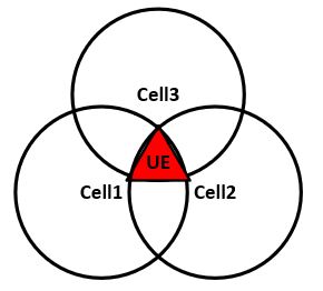
The art is to triangulate the UE as accurate as possible. The triangulation means determining the timing measurements from at least 3 reference points and calculating the distance from these points to locate the UE.
The following diagram illustrates triangulation of UE by three cellular sites.

In practice, it boils down to detecting signals from the Cellular Sites, estimating the relative timing based on the signal strength and estimation of appropriate part of the sub-frame of cellular packet format/protocol as well as digital signal processing algorithms which are based on statistical analysis.
The calculated location of the UE would be to within a “Triangle”, or uncertainty. The smaller triangle the better the signal detection and/or algorithms.
Partner with ORTENGA for location finding HW/Algorithm design and development.
Why DSP Algorithms are implemented via Fixed Point in FPGA?
Currently, typical HW simulators such as Matlab use 64-Bit representations for numbers.
1 Bit can be defined as distinguishing an in-distinguishable.
Typical DSP algorithms do not need such wide, 64-Bit, word for its variable to arrive at acceptable computation tolerances. In fact, implementing 64-Bit Algorithm could be costly in terms of power consumption, required memory, and computation time, critical algorithm metrics.
On the other hand, lack of adequate Word Length could cause convergence issue, inaccurate results, and erroneous decision makings.
Proper Algorithms are optimized for all of the above metrics.
Algorithm designer can calculate the required number of Bits, Word Length, for tolerable error in computation. This calculation is called Floating Point to Fixed Point Conversion.
There are many techniques to make the conversion and even Matlab can do that for you.
However, there is more efficient technique which will be faster to make the conversion and ORTENGA utilize that.
Partner with ORTENGA for DSP Algorithms and FPGA implementations.
Antenna Tuners
Historically antenna tuners meant any passive interface impedance matching device between the antenna and the RF front end. This terminology has carried over to UE and/or mobile devices. In addition, as the need for multiple bands antenna increased, the need for antennas that can operate at multiple bands became prime interest of ODMs. Nowadays, antenna tuning could either imply antenna impedance tuning or antenna aperture tuning. The aperture tuning mechanism is part of antenna structure and changes antenna resonance frequency, hence operating at multiple bands.
Partner with ORTENGA to design and develop Antenna Tuning Algorithms for your new product.
SLL Management Algorithm Flow
Side Lobe Level, SLL, are undesired radiation characteristic of any antenna or antenna arrays.
Many companies spent significant amount of time and resources during the prototype development phase to mitigate SLL and qualify/certify the radiation pattern by FCC. The issue which remains is two folds even after they succeed to meet FCC and regulatory requirements.
First, the SLL mitigation technique used are not optimum design performances and typically sacrifice antenna gain and power efficiency of Power Amplifier to meet regulations. This in turn translates to lower C/N and/or Eb/N0, therefore lower throughput. In other words, the transmitter suffers power efficiency as well as optimum throughput, two critical metrics for any transmitter in exchange for mitigating SLL, which should have been part of original design to begin with, hence lack of optimum design.
Spending resources to design efficient power amplifier, yet backing off from efficiency sweet spot of Power Amplifier due to undesired and uncontrolled SLL defeats the purpose of the overall system metrics; that power efficiency and throughput, both of which impact bottom lines of the network operator.
Second, the additional time which takes for trial and error is reducing the chances of being in the market during the window of opportunity.
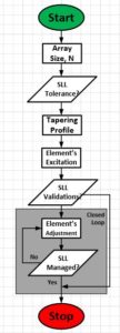
ORTENGA SLL Management Algorithm is proactive design and embedded during the development phase to expedite TTM while producing optimum design trade-off Gain vs. SLL, hence power efficiency and throughput, below algorithm flow.

Partner with ORTENGA for design and development of radio algorithms and implementations in your new product.
Beam Tracking Algorithm Flow
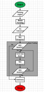
Beam Tracking Algorithm is utilized when there is beamforming and mobility either at transmitter or receiver.
The following diagram illustrates top level algorithms flow interactions, namely; Beamforming, SLL management, and Beam tracking.

It is worth mentioning that although the high level flow diagram is similar yet actual flow diagram may change depending on the applications and use cases. For instance, in some use cases or applications, there is need for Target Acquisition Algorithm, before beam tracking algorithm of the target is invoked.
Partner with ORTENGA in design and development of any of the above algorithms for your new product.
Machine Learning Algorithms
There are many design problems which do not have known theoretical or analytical solutions, yet they have practical applications, therefore demand in the technical market space.
M2M communications require some level autonomous in learning and decisions making to ensure, no human interactions.
If you have any of these problems, ORTENGA has subject matter expertise to help you define the scope and then provide appropriate ML algorithm to address that.
Clutter Rejection Algorithm
Radar clutter reduces SNR therefore it reduces the detection, consequently the radar capability in identify the object of interests.
Regarding Autonomous Automotive, reducing the clutter enhances the radar in identifying and distinguishing various objects’ scatterer on and near the road.
Augment ORTENGA in your Radar design and development.
Direction Finding Algorithms
Bat has direction finding sensors and organic intelligence or algorithm which helps them to navigate, detect and track prey. Bat uses audio signals, sonar anywhere between 15 to 200 KHz to echolocate prey and navigate its surroundings.
The speed of sounds in the air is 343 m/s at 20°C air. That makes the wavelength anywhere between 15 to 30 cm. Yet, bat has spatial resolution as small as 0.3 mm, which is 2 orders of magnitude smaller than operating wavelength. This implies that bat direction finding algorithm is phase-based interferometry. In fact, bat temporal resolution is anywhere between 10 to 400 ns which corroborates phase interferometry direction finding algorithm.
To echolocate, there are at least two sensors/ears are required. Any waveform has amplitude, frequency, and phase attributes. At least one of the waveform attributes can be compared by the two sensors to echolocate the source of that signal.
The same techniques can be used for an emitter of electromagnetic signals.
Orca has direction finding sensors and organic intelligence or algorithm which helps them to detect, identify, and track prey. Orca has a meticulous eating menu and does not eat outside of their menu. They are highly intelligent and works as team/family for developing hunting skills for that particular prey.
The speed of sound in ocean water is 1500 m/s. Orca also use sonar with frequency between 0.5 to 25 KHz with the peak energy between 1 to 6 KHz. That makes the operating wavelength anywhere between 0.25 to 1.5 m. With this wavelength range and the size of orca and menu targets, it can be deduced that orca can either use amplitude or phase-based interferometry.
Phase based interferometry is more accurate technique for direction finding of the emitter.
Electromagnetic signals can be located with direction finding algorithms either amplitude or frequency, depending on the required spatial resolution, available HW, and the baseline of the multiple sensors.
Human uses the ears to echolocate the source of the received audio using amplitude comparison direction finding.
ORTENGA helps businesses to identify required technical features to realize their business goals.
MUSIC Algorithm
Multiple Signals Classification, MUSIC is an advanced direction-finding algorithm.
MUSIC algorithm uses Jacobi algorithm to find Eigenvalues and Eigenvectors of incoming multiple signals in order to reduce the computations and determine real time direction of EM emitters.
Jacobi algorithm is an iterative technique to determine the solution to a system of linear equations.
MUSIC is an effective real time algorithm for accurate spatial resolution of multiple EM emitters and/or multiple sensors in the environment.
ORTENGA helps businesses to identify required technical features to realize their business goals.
Envelope Tracking Algorithm
Envelope Tracking, ET, Algorithm have mitigated Power Added Efficiency, PAE, of Power Amplifiers, PA, in UE as well as eNB infrastructure during that past decade.
It is well known that maximum PAE is reached when PA is near compression point. However, operating PA at or near compression point produces signal distortions due to non-linearity behavior of PA which effectively reduces EVM of transmitting signal, system KPI.
In order to mitigate the signal distortion, the PA nonlinearity can be simulated or characterized. Then the desired signal can be distorted intentionally prior feeding the PA in such a way that after the PA amplification, the desired signal becomes linear again. This algorithm is called Digital Pre Distortion, DPD, and widely used in UE, eNB, and gNB infrastructures.
ORTENGA has seasoned engineering from ASIC, SATCOM, radar, and mobile terrestrial radio communications industries in HW, FW, and SW engineering disciplines.
How to calculate Exact Number of Bits for DSP Algorithms?
Digital Signal Processing, DSP, algorithms are typically coded in MATLAB with floating point numbers. Whereas the implementation of the same algorithm in HW/FPGA is bounded by limited number of bits, therefore, there is question of how many bits are actually required such that the given algorithm has adequate accuracy.
The short answer is that the exact number of bits can be analytically calculated similar to ADC or DAC’s ENOB and it can be validated via fixed point in MATLAB to ensure the exact number of bits produce the expected accuracy.
ORTENGA has seasoned engineering from ASIC, SATCOM, radar, and mobile terrestrial radio communications industries in HW, FW, and SW engineering disciplines.
Singular Value Decomposition, SVD Algorithm
SVD matrices are utilized in many engineering disciplines as well as finance industry.
In radio communications system, Multi Input Multi Output, MIMO architecture requires calculating inverse matrix of the channel.
The inverse matrix calculations are computationally very expensive, O (n3), and time and power consuming.
SVD matrix is utilized to diagonalize the channel matrix, therefore significantly reducing the computations for real time in mobile handset.
Finance industry use SVD to compress financial data, representing data using “less information” to save memory space. SVD can be thought as data compression technique.
ORTENGA helps businesses to identify required technical features to realize their business goals.
ORTENGA is comprised of seasoned and skillful engineers who collaborate on innovative design in entrepreneurial environment to accomplish clients’ project.
Partner ORTENGA in your next product concept, design, and development to realize that business goal.
ORTENGA has seasoned engineering from Autonomous Automotive, SATCOM, radar, Smart City, WiFi, and Mobile Terrestrial Radio Communications industries in Antenna, ASIC, HW, FW, and SW engineering disciplines.
State Machine, AI, and Human
State machine is a model which describes a system behavior or its transitions by defining its state and input required for each transition.
Perhaps the simplest system is electrical light bulb where state machine is electrical switch. There are two states, On or Off. The electrical switch can force the state change from On to Off or vice versa.
Another yet more complicated system is 3 floors’ elevator. There are 3 states or floors. Depending on the state or floor level and which button is pressed, the elevator moves in certain up or down direction.
Human is the most sophisticated known system. Our emotions are the states, e.g., angry, happy, rational, sad etc. Our response is different depending which state of being we are in and how is that input is delivered.
Artificial Intelligence, AI is another system. Your question (input) to AI, puts AI in a certain state depending on the programmer knowledge and definition of boundary conditions. Therefore, the response would depend on that state and your question (input).
Given AI system and finite number of states, the response to your question is finite in numbers and may differ somewhat from time to time depending how you ask your question and initial conditions of AI.
Human state of mind or emotion can change. Some of us are triggered by external events or words. Therefore, our response would be different depending our state of being or emotion.
The easiest way to control our emotion can be similar to electrical switch. Breath in and breath out could be human emotional switch. Our state of mind would determine how we respond to others’ request.
Human with appropriate state of mind, curiosity, willingness, and calculated risk-taking initiative can discover new things or new ways of doing things, hence innovate and progress.
Partner with ORTENGA to design and develop state machine for your system.