- Signal Modulation
- Radar Waveform
- Radio Communications and Radar Similarities
- Digital Data Packet Quality of Service, QoS
- Radar Ambiguity Function
Signal Modulation
In radio communication, the signal of interest is typically not at the radio frequencies.
In general radio frequencies, RF refers to frequencies at which a realizable size antenna can be utilized to covert electrons to photons, hence radio wave propagations. Therefore, there are at least two frequencies, one of the signals the other of the carrier, RF. The carrier is meant as the means to propagates between transmit to receive antennas. The method in which the signals of interest alter the carrier frequency, RF, is called modulation.
Here are some legacy modulation techniques which everyone uses in their daily life.
Amplitude Modulation, aka AM used in your car AM radio. The signals of interest alter the carrier amplitude, i.e. the amplitude of the carrier is the information which is meant for the receiver. This legacy modulation technique is susceptible to multipath fading. As you drive under a highway bridge, you notice that the AM radio audio signal is momentarily lost and comes back. This phenomenon is caused by multiple bounces of radio signal waves against the bridge and reaching your car radio. These radio waves sometime cancel each other and other time add constructively. The radio wave cancellation is fading of the signals of interest.
Frequency Modulation, aka FM used in your car FM radio to address multipath fading. While you are listening to FM radio under the highway bridge, you would not experience any loss of signal.
The above modulations are analog method of modulation. Nowadays, there more advance digital modulations. Digital modulations have three advantages over analog modulation.
- Spectrally more efficient over analog counter part
- More immune to noise, i.e. requires lower SNR for signal detections and discern
- More secure, as digital code changed between the transmitter and receiver
For the above reasons, digital modulations are ubiquitous.
Binary Phase Shift Keying, aka BPSK is the most basic digital modulation. The signals of interest are binary and embedded in the phase, 0 vs. 180 degrees of the carrier.
Quadrature Phase Shift Keying, aka QPSK is another digital modulation. The signals of interest are 2 bits and embedded as 45, 135, 225, 315 degrees phase of the carrier.
The binary codes are digital alphabet of modulation language.
It turns out the as the number of alphabets, bits increased, the more information can be encoded in the carrier, i.e. more spectrally efficient, bps/Hz.
On the other hand, as the number of alphabets, bits increased, additional signal to noise, SNR is required. In other words, the signals of interest are less immune to noise, consequently, additional power is required.
This is a challenge that communication engineering needs to balance, the trade off between spectral vs. power efficiency, hence digital modulation scheme design.
Work with ORTENGA to design your product.
Radar Waveform
Radar waveform is typically specified by its Pulse Width, PW and Pulse Repetition Interval, PRI aka Pulse Repetition Frequency, PRF.
These parameters are driven from targe of interest attributes, namely; its range, radial velocity, spatial resolution, etc.
The electromagnetic echo returned from the target is compared against the original waveform, i.e. matched filter, to maximize SNR and detect the target and decipher its attribute, range, radial velocity, the size.
The higher SNR, the higher the probability of detection and lower false alarm rate. The SNR requirement is higher if the target needs to be tracked.
SNR is dependent on the electrical appearance of the target, aka radar cross section, range, frequency, background noise, aka clutter.
The operating wavelength and aperture size determine the spatial resolution. Therefore, radar frequency planning should be meticulously selected based on the technical objectives.
When there are multiple targets with various attributes, radar waveforms have to be tailored for each target of interests. This becomes challenging at best if not impossible, that is where MIMO radar comes in to mitigate.
For the above reason, radar waveform has to be meticulously designed to meet technical objectives.
Hire ORTENGA for your radar design and development.
Radio Communications and Radar Similarities
Radio Communications and Radar have been two distinct technologies in their own industries. However, in the past decade, the advancement of technologies both in Academia as well as implementations and integrations of radio and processor in to more devices from handheld to terminal based have led to some interesting overlaps between these two industries. This blog will briefly walk through the similarities and overlap of implementations.
Perhaps the most difficult problem of Terrestrial radio communications is fading mitigation. Fading is not only function of frequency but also of the environment or terrain. This makes it new problem to solve, every time, the radio is supposed to operate at different frequency or environment.
Radars typically operate in open environments and the small echo from their targets arrives at receiver directly. Any multipath echo is too small in amplitude to be resolved with meaningful information. On the other hand, the radar target aspects impact the radio signal similar to what environment do to radio communication signal. Target scintillation is well known issue to radar industries. Radar target scintillation can easily vary the amplitude of echo signal as much as 10dB for milli-radian variation of target aspect. Target scintillation is also function of frequency and target aspects.
Radar Cross Section, RCS, subject matter experts spend their life time to model various target at different frequencies to model radar echo signal behavior to design appropriate radar.
Multipath Fading in Terrestrial Communications and Target Scintillation of Radar Cross Section, RCS, requires appropriate waveform design. In Communications, the waveform depends on environment modulating this waveform and how to retrieve or reconstruct the waveform at the receiver. To optimize the waveform for maximum SINR, the waveform is carefully designed for its timing metrics.
In radar, the waveform depends on target modulating this waveform and how to retrieve desired information about the target. Target “finger print” is on the echo waveform. To optimize the waveform for maximum SINR, the waveform is carefully designed for its timing metrics.
MIMO technology utilized orthogonal waveforms from multiple transmit antennas, independent waveform, to arrives at the receivers and be combined in such a way that SINR is fairly constants for all receivers.
In case of MIMO radar, each orthogonal waveform is designed to one desired metrics of target and the received signals can be processed to retrieve the desired metric.
There are typically 4 models that are used to simulate the behavior of target RCS, Swerling 1, 2, 3, & 4.
Swerling models 1& 2 are based on independent and identical distribution, iid, scatters of target aspect, which is effectively similar to Rayleigh fading model. Swerling model 1 and 2 are slow and fast RCS variations with respect to dwelling time, i.e. slow and fast fading with respect to symbol time in radio communications.
Swerling models 3 & 4 are based on specular RCS aspect, similar to Rician fading with dominant path.
Swerling models 3 and 4 are slow and fast RCS variations with respect to dwelling time, i.e. slow and fast fading with respect to symbol time in radio communications.
It may be surprise to some as how similar the radar and terrestrial radio communications are, yet it worth to note it is behavior of radio waves in environment whether it is used for communications or radar.
ORTENGA is a consulting firm with Subject Matter Expertise in both Radio Communications and Automotive Radar applications.
ORTENGA designs and develops Radio Communication or Radar Waveform.
Digital Data Packet Quality of Service, QoS
Digital Data Packet Quality of Service, QoS should be application dependent.
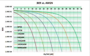
For audio signal, e.g., phone call, human ears cannot distinguish better than 1 bit error in 1000 bits, i.e., BER = 1e-3.
Therefore, the QoS for audio call is BER ≤ 1e-3.
For visual signal, e.g., TV movie or picture human eyes have much higher resolution, 1 bit error in 1000,000,000, i.e., BER = 1e-9.
Therefore, the QoS for TV picture is BER ≤ 1e-9.
Combining these observations with Water Fall Curves, they reveal that as the BER decreases required Eb/N0 increases.
The Water Fall Curves reveal that as the spectral efficiency increase the required Eb/N0 is also increases, for given QoS which depends on the application.
ORTENGA has seasoned engineering from Autonomous Automotive, SATCOM, radar, Smart City, WiFi, and Mobile Terrestrial Radio Communications System industries in Antenna, ASIC, Algorithm, HW, FW, and SW engineering disciplines.
Partner with ORTENGA to define and develop your new product.
Radar Ambiguity Function
Radar waveform can be designed for either range or range rate of change, i.e., velocity which shows its signature in Doppler frequency shift.
Therefore, radar designers have to decide what is it about the target of interest which has priority and want the radar to measure.
Once the waveform is designed based on the radar requirements, then that waveform is evaluated using the Radar Ambiguity Function for its performance under the appropriate conditions.
Ambiguity function reveals the uncertainty of that waveform for range and Doppler frequency under various conditions
ORTENGA helps businesses to identify required technical features to realize their business goals.
ORTENGA has seasoned engineering from Autonomous Automotive, SATCOM, radar, Smart City, WiFi, and Mobile Terrestrial Radio Communications System industries in Antenna, ASIC, Algorithm, HW, FW, and SW engineering disciplines.
Partner with ORTENGA to define and develop your new product.