- Antenna Array Far Field Radiation Pattern
- Antenna Array with Mutual Couplings
- Antenna Array Factor over Ground Plane
- Vivaldi 2D Antenna Array, aka Vivaldi Egg Crate Array
- Side Lobe Level in Antenna Radiation Pattern
- 16×16 Antenna Array Radiation Pattern with Beam Forming and SLL
- Why some applications use Antenna Array?
- MIMO vs. Beamforming
- Antenna Array Feed Network
- Interference Cancellation
Antenna Array Far Field Radiation Patterns
Antenna arrays are used to achieve higher directivity relative to the array element.
The radiation pattern of an array can be computed as
Far Field Radiation Pattern = |EF * PF * AF|2
where, EF, PF, and AF are Element Factor, Pattern Factor, and Array Factor.
Element Factor is infinitesimal factor of single element antenna
Pattern Factor is radiation pattern of single antenna due to its current distribution over the antenna
Array Factor is radiation pattern of array due to isotropic element
Each of the above factors can be computed standalone and their products is Far Field Radiation Pattern of the array.
For instance, Marconi-Franklin Linear array antennas are stacked 3 dipole antenna.
The element factor is Hertzian dipole pattern.
The Pattern factor is the radiation pattern of single dipole due to sinusoidal current excitation or distribution. And the Array factor is the pattern due to isotropic elements array.
ORTENGA helps businesses to identify required technical features to realize their business goals.
ORTENGA provides structured engineering leadership across antenna architecture, realization planning, integration, and deployment validation to reduce downstream realization risk and improve alignment between engineering execution and business objectives.
→ Explore ORTENGA Structured Execution Model
→ Assess Your Project Risk Profile
Antenna Array with Mutual Couplings
When calculating antenna array pattern for complete accuracy, the pattern of an array antenna must include the variations in the excitation currents as well as the pattern of each element acting under the influence of all coupling effects.
This is a difficult task if not impossible; however there are 2 techniques for addressing this problem, namely; isolated element and active element pattern approach.
In the isolated element pattern approach, the coupling effect is accounted for in the current excitation and is appropriate for very large arrays.
In the active element pattern approach, all coupling effects are accounted for through the active element.
ORTENGA helps businesses to identify required technical features to realize their business goals.
ORTENGA provides structured engineering leadership across antenna architecture, realization planning, integration, and deployment validation to reduce downstream realization risk and improve alignment between engineering execution and business objectives.
→ Explore ORTENGA Structured Execution Model
→ Assess Your Project Risk Profile
Antenna Array Factor over Ground Plane
5G NR, gNB, LEO SATCOM, radar, and WiGig rely on beamforming, therefore Active Electronically Scanned Antenna Array, AESA. Typically AESA has ground plane, consequently image theory must be utilized to arrive at proper radiation pattern of AESA for simulation and therefore in actual applications. This particularly becomes important and critical for implementing Beamforming, Beam steering, and SLL management algorithms.
The appropriate simulations enable the architect, system design, and managements to validate assumptions made for feasibility of design. ORTENGA provides simulation tools to validate your design and goes beyond what appropriate Phase Array Tool Box or SystemVue provide, independently.
Augment ORTENGA into your architect and system design teams to validate design before its implementations.
ORTENGA provides structured engineering leadership across antenna architecture, realization planning, integration, and deployment validation to reduce downstream realization risk and improve alignment between engineering execution and business objectives.
→ Explore ORTENGA Structured Execution Model
→ Assess Your Project Risk Profile
Vivaldi 2D Antenna Array, aka Vivaldi Egg Crate Array
It is well known that Vivaldi antenna element scales with wavelength due to its taper aperture topology.
Consequently, Vivaldi antenna has broadband bandwidth.
2D Vivaldi antenna array could be designed for broadband bandwidth in mmW band.
This would be an ideal beamforming antenna array for both radio communication and radar systems that covers wide bands.
ORTENGA provides structured engineering leadership across antenna architecture, realization planning, integration, and deployment validation to reduce downstream realization risk and improve alignment between engineering execution and business objectives.
→ Explore ORTENGA Structured Execution Model
→ Assess Your Project Risk Profile
Side Lobe Level in Antenna Radiation Pattern
Side Lobe Level, SLL in antenna radiation patter is undesired.
Antenna SLL picks up unwanted (noise) signals from the undesired directions in the radio communication or radar systems.
While the main lobe of radiation pattern is supposed to pick up the desired signal in the radio communication or radar systems.
It turns out that SLL can be controlled by adjusting the current/voltage distributions on the antenna aperture.
The smoother the current/voltage distributions roll off from its peak to zero at the aperture edge, the smaller SLL.
In contrary, the sharper the current/voltage distribution from its peak to zero at the aperture edge, the narrower radiation beamwidth.
Therefore, there is a trade off between antenna beamwidth and SLL.
Antenna designer can effectively control SLL if s/he understands the radio communication or radar system use cases.
ORTENGA provides structured engineering leadership across antenna architecture, realization planning, integration, and deployment validation to reduce downstream realization risk and improve alignment between engineering execution and business objectives.
→ Explore ORTENGA Structured Execution Model
→ Assess Your Project Risk Profile
16×16 Antenna Array Radiation Pattern with Beam Forming and SLL Management Algorithms
Figure 1 diagram illustrates a 16×16 (64 Square Wavelengths) rectangular antenna array which is typically utilized in 5G infrastructure, gNB, 802.11ay, WiGig, Fixed Wireless Access, FWA, Short Range Radar, SRR, or eHealth nowadays at mmW frequencies. Keep in mind that this array can be integrated as part of mMIMO as well.
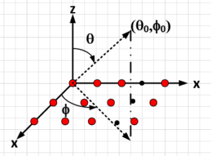 Figure 1: 16×16 Rectangular Antenna Array in x-y plane
This 256 elements array has considerable directivity and gain. The additional gain of array over single element antenna is 21 – 24 dB, which enables dB per dB better SINR in the radio link, consequently higher Spectral Efficiency, SE. It is worth mentioning that higher SINR or effectively Eb/N0 results in higher order modulation alphabets, [bps/Hz]. A higher order modulation alphabet is directly proportional to spectral efficiency with proportionality constant of Code Rate, i.e. SE = (bps/Hz) * CR. This is in essence the reason behind 5G NR throughput or better range/velocity resolution in radar applications.
Figure 2 diagram illustrates radiation pattern of the array when it is pointing to broadside or theta0 = 0°. For this configuration, the directivity and gain are at highest, whereas the beamwidth is narrowest.
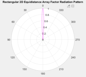
Figure 2: 16×16 Antenna Array Beamforming at Broadside, theta0 = 0°
Figure 3 illustrates 16×16 AF Universal radiation pattern for theta0 = 0°, where HPBW = ~7°.
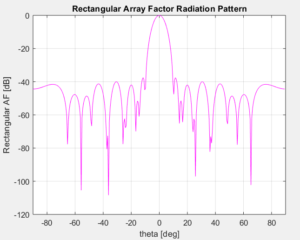
Figure 3: 16×16 AF radiation pattern Universal Plot for theta0 = 0°
Figure 4 diagram illustrates array pointing at theta0 = 45°.
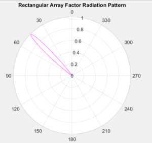
Figure 4: Antenna Array Beamforming at 45° from Broadside
Figure 5 illustrates Universal plot of the array at theta0 = 45°.
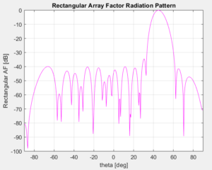
Figure 5: 16×16 AF Universal Plot at theta0 = 45°
Notice the HPBWtheta = 9° has increased, i.e. aka beam broadening, as the array pointing away from broadside. That in turns results in gain roll off ~2dB, which is expected due to decrease in array aperture size.
Figure 6 illustrates Universal plot of the array pointing at phi0 = 55° for theta0 = 45° plane or cut, HPBW = ~9°.
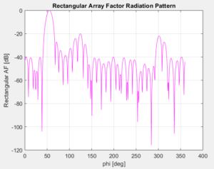
Figure 6: 16×16 AF radiation patter for theta0 = 45° plane
For the antenna array the SLL can be designed to not exceed specifications with minimum penalty in AF directivity or equivalently the gain. For this optimized design, the directivity trade-off is ~0.5dB, yet SLL are typically improved more than several dB at the least. Therefore, during the operation of overall radio system, the transmitter power efficiency is optimized and yields better overall C/N or SINR, consequently, better spectral efficiency is achieved.
Any other (theta,phi) pointing angle can similarly be synthesized by the 16×16 antenna array. The above figures are just examples of antenna array capabilities.
These radiation patterns are for isotropic sources and depending on your system impairments additional noise sources can be introduced in to simulations to mimic the system under analysis and synthesis. For instance, ORTENGA can include amplitude taper noise and/or inter-element phase error based on HW implementations and limitations, two common errors that contribute to KPI of any antenna array.
ORTENGA has modeling with noise profile for beamforming and SLL performance for various tapering profiles. Also, ORTENGA has capabilities to design larger array size, circular, and/or concentric shapes. ORTENGA algorithms provide minimum SLL for minimum beamwidth, effectively optimum antenna array gain. There is misconception that maximizing antenna array gain provides better C/N. However, in practice the overall transmitter must meet FCC emission regulation during the operation, which forces the transmitter to back off from maximum power due to unwanted SLL, therefore under-utilizing transmitter power efficiency.
ORTENGA provides structured engineering leadership across antenna architecture, realization planning, integration, and deployment validation to reduce downstream realization risk and improve alignment between engineering execution and business objectives.
→ Explore ORTENGA Structured Execution Model
→ Assess Your Project Risk Profile
Why some applications use Antenna Array?
Antenna Array is group of antennas that are either in linear or planar formation and interconnected to produce a more directional radiation pattern.
The amplitude pattern on array element controls the side lobe level, whereas the inter-element phase shift controls the beam pointing angle.
The radiation beam pointing angle is called, beam boresight.
The additional directivity is proportional to the number of elements in the array.
In planar formation, the more elements in a given axis increases the directivity or reduces the beamwidth for that axis.
It is worthwhile to mention that not every group of antennas form an array, e.g., MIMO.
MIMO utilizes group of antennas to achieve better SINR by exploiting multipath, i.e. spatial diversity.
The antennas in MIMO could radiate different or distinct signals, whereas in the antenna array, they radiate the same signal.
Here is a related content, MIMO vs. Beamforming.
ORTENGA provides structured engineering leadership across antenna architecture, realization planning, integration, and deployment validation to reduce downstream realization risk and improve alignment between engineering execution and business objectives.
→ Explore ORTENGA Structured Execution Model
→ Assess Your Project Risk Profile
MIMO vs. Beamforming
MIMO is based on multiple antennas similar to antenna array however each antenna is working independently of other antennas. The overall data is decomposed to lower data rate and each antenna is transmitting portion of that data, independently. In essence MIMO is using spatial diversity and multiplexing for very high data rate transmission. The spacing between each antenna is a wavelength to create adequate isolation while uncorrelated signals are picked up by each antenna.
Beamforming is achieved via Phased Array Antennas. The Phased Array Antennas are based on array technologies which have been used extensively in military applications in the past 4 decades. The antenna arrays electronically steers the beam to illuminate the intended target. The beam steering occurs via changing the relative phase of each antenna element, such that the overall beam is formed of construction of Electromagnetic Waves at desired direction in the far field and produce higher SNR compare to single antenna at the receiver end. The Phased Array Antennas are working together to achieve high gain/directional antenna, hence higher SNR at the receiver. The spacing between each antenna element is typically half wavelength to avoid grating lobe.
5G Technology will be utilizing massive MIMO as well as Beamforming, BF. Massive MIMO is intended for below 6GHz, whereas BF will be used for mmW bands (i.e. where wavelength is in order of mm, e.g. 30GHz).
ORTENGA provides structured engineering leadership across antenna architecture, realization planning, integration, and deployment validation to reduce downstream realization risk and improve alignment between engineering execution and business objectives.
→ Explore ORTENGA Structured Execution Model
→ Assess Your Project Risk Profile
Antenna Array Feed Network
Antenna array requires elaborate feed network to meet technical requirements.
The feed network impacts the bandwidth, insertion loss, isolation, polarization, and SLL.
Insertion loss would impact the overall efficiency and gain.
Therefore, the feed network requires careful design considerations, trade off analysis among technical requirements, and implementations of proper feed network topology.
ORTENGA provides structured engineering leadership across antenna architecture, realization planning, integration, and deployment validation to reduce downstream realization risk and improve alignment between engineering execution and business objectives.
→ Explore ORTENGA Structured Execution Model
→ Assess Your Project Risk Profile
Interference Cancellation by Antenna
Radio interference cancellation is a technique in which the interfering radio signal is suppressed by placing a null in radiation pattern of antenna or antenna array systems.
Far Field or Fraunhofer radiation pattern of an antenna is function of current or field distribution over the antenna aperture.
Antenna proximity can be divided to 3 regions; Reactive near field, Radiating /Fresnel near field, and Far Field/Fraunhofer.
Radio communication energy is targeted for Far Field of an Antenna.
The idea of radio interference cancellation via radiation pattern is similar to suppressing an unwanted signal via filter.
In fact, antenna is a “spatial filter”, see Similarities of Filter vs. Antenna, posted on August 5th. This technique assumes that the direction of interfering signal is prior knowledge or dynamically can be detected.
By forming antenna arrays, the radiation pattern of over antenna array can be adjusted dynamically via phase relationship between each antenna feeding.
Alternatively, if the radio interfering signal is placed at side lobe of the radiation pattern, the unwanted signal strength can be adjusted via current or field distribution of antenna array.
ORTENGA helps businesses to identify required technical features to realize their business goals.
ORTENGA provides structured engineering leadership across antenna architecture, realization planning, integration, and deployment validation to reduce downstream realization risk and improve alignment between engineering execution and business objectives.