- Horn Antenna
- Horn Antennas: The Reference That Defines RF and Radar Performance
- Slotted Waveguide Antenna
- Electromagnetic Angle of Arrival or Direction-Finding Algorithms Dependency on Antenna
- Circularly Polarized Antenna Axial Ratio
Horn Antenna
Horn is an aperture antenna with moderate to high gain, e.g. 10 – 20 dBi.
Horn antenna has good radiation efficiency and well impedance matching property due to its waveguide transmission line extension which can be tapered.
Horn antenna has excellent mathematical model to experimental measured data. Consequently, horn antennas are used as the reference antenna for antenna chambers.
ORTENGA provides structured engineering leadership across antenna architecture, realization planning, integration, and deployment validation to reduce downstream realization risk and improve alignment between engineering execution and business objectives.
→ Explore ORTENGA Structured Execution Model
→ Assess Your Project Risk Profile
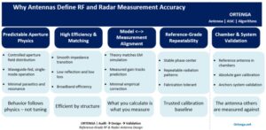
Horn Antennas: The Reference That Defines RF and Radar Performance
From Analytical Models to Chamber Validation—Why Horns Still Set the Standard
When accuracy matters, complexity is rarely the answer. In RF and radar systems, the most trusted antenna is not the most exotic one—but the one whose behavior is fully understood, mathematically predictable, and experimentally repeatable. Horn antennas endure as the reference standard because their performance aligns cleanly across theory, simulation, and measurement—making them the anchor for calibration, validation, and system confidence.
What Is a Horn Antenna?
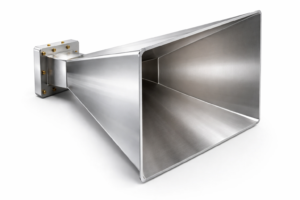
A horn antenna is an aperture antenna that provides moderate to high gain, typically in the 10–20 dBi range, with well-controlled radiation characteristics. Structurally, it is a flared extension of a waveguide, designed to transform a guided electromagnetic mode into a free-space radiating wave with minimal reflection and loss.
This seemingly simple geometry is precisely what gives horn antennas their enduring value: they are governed by physics that can be modeled accurately and verified reliably.
Why Horn Antennas Perform So Predictably
Horn antennas exhibit high radiation efficiency and excellent impedance matching, enabled by the gradual taper of the waveguide-to-aperture transition. This controlled transition minimizes reflections, suppresses higher-order modes, and produces stable, repeatable radiation patterns.
Unlike many compact or highly optimized antenna structures, horn antennas rely far less on tuning, compensation, or empirical correction. Their performance is dominated by geometry and wavelength—parameters that are well understood and analytically tractable.
Frequency Considerations
Horn antennas are typically utilized at X-band and above, where waveguide dimensions are manageable and the horn’s predictable aperture behavior enables high gain and accurate radiation control. At lower frequencies, horn antennas become prohibitively large and heavy, as waveguide cross-sections and flare lengths must increase to maintain efficient single-mode operation and gain.
This natural frequency scaling is why horn antennas are most often found in radar, satellite communications, and RF measurement environments, rather than in size- or weight-constrained platforms.
Why Horn Antennas Are Used as Reference Antennas
One of the defining strengths of horn antennas is the exceptionally tight alignment between analytical models, electromagnetic simulations, and measured data. Gain, beamwidth, sidelobe levels, and phase behavior can be predicted with high confidence—and verified experimentally with minimal discrepancy.
Because of this, horn antennas are widely used as reference antennas in anechoic and antenna test chambers, serving as the calibration baseline against which other antennas and systems are measured. When absolute gain, pattern accuracy, or measurement traceability matters, horn antennas are often the benchmark.
From Component to System Confidence
Horn antennas are not chosen because they are novel or compact. They are chosen because they are trustworthy. In RF and radar systems, where calibration errors propagate quickly and measurement uncertainty can undermine entire programs, reference-grade behavior is more valuable than aggressive optimization.
Whether validating a radar front end, calibrating a measurement chamber, or anchoring system-level performance claims, horn antennas provide a stable foundation upon which accurate decisions can be made.
ORTENGA designs and develops horn antennas with a system-level mindset, ensuring that performance requirements, mechanical constraints, and validation objectives are aligned from the outset. From defining reference-grade specifications to supporting chamber calibration and system verification, our work ensures that horn antennas perform not just on paper—but in practice.
Audit → Design → Validate is not a slogan; it is how reference antennas earn trust.
When RF or radar performance must be measured, validated, and defended, reference-grade behavior matters more than novelty.
ORTENGA provides structured engineering leadership across antenna architecture, realization planning, integration, and deployment validation to reduce downstream realization risk and improve alignment between engineering execution and business objectives.
→ Explore ORTENGA Structured Execution Model
→ Assess Your Project Risk Profile
Slotted Waveguide Antenna
Slotted Waveguide Antenna, SWA is used in high power and high gain radar applications.
Waveguide is utilized both at transmission line as well as the antenna.
Waveguide is known for its high power, low loss, and temperature control, consequently high-power pulsed radar applications.
ORTENGA provides structured engineering leadership across antenna architecture, realization planning, integration, and deployment validation to reduce downstream realization risk and improve alignment between engineering execution and business objectives.
→ Explore ORTENGA Structured Execution Model
→ Assess Your Project Risk Profile
Electromagnetic Angle of Arrival or Direction-Finding Algorithms Dependency on Antenna
Electromagnetic, EM Angle of Arrival, AoA or Direction Finding, DF algorithms’ performance depends on the EM sensors, i.e. antennas utilized.
Typically, there is a distinction between AoA and DF algorithms, even though their names appear similar, yet in the radar industry AoA and DF have different implications.
AoA refers to angle in which EM wave source is located in azimuth plane or plane of reference.
Whereas, DF refers to AoA plus range to the EM source, i.e. geo location.
Therefor DF algorithm requires additional inputs relative to AoA algorithm.
AoA or DF requires at least two sensors for differential measurement of either amplitude, time, phase, or envelope of the EM waves.
Antennas utilized for EM sensing in AoA or DF are major contributors to the error in the measurements, therefore these antennas have to be specified, designed and developed with the AoA or DF performance objectives in mind.
ORTENGA provides structured engineering leadership across antenna architecture, realization planning, integration, and deployment validation to reduce downstream realization risk and improve alignment between engineering execution and business objectives.
→ Explore ORTENGA Structured Execution Model
→ Assess Your Project Risk Profile
Circularly Polarized Antenna Axial Ratio
Circularly Polarized, CP antennas are utilized in SATCOM and Radar applications.
When antenna CP is specified and every tenth of dB in SNR has to be accounted for to achieve proper radio communication link or DF algorithm performance, then the accuracy of the antenna CP have to be quantified.
The metric to quantify antenna CP is called Axial Ratio, AR.
AR is the ratio of major to minor axis of an ellipse.
A line can be thought of an extreme ellipse where the minor axis is zero.
A circle can be thought of an ellipse where the major and minor axes are equal.
ORTENGA provides structured engineering leadership across antenna architecture, realization planning, integration, and deployment validation to reduce downstream realization risk and improve alignment between engineering execution and business objectives.