Why Digital Communications use Data Packet?
Data Packets are used in digital communication to enhance transmitter and receiver synchronization as well as efficiency.
It is well known that digital data enhances spectral efficiency, noise immunity, and security.
Data Packets allow the transmitter and receiver to synchronize and authentication before data exchange.
Data Packets also comprised of error correction codes which allow some errors to be corrected without retransmission of the original data.
802.11ay Packet Format
802.11ay is the next generation of WiGig, aka 802.11ad, with mission to enable Augmented Reality, AR, and Virtual Reality, VR, and wireless backhauling applications.
802.11ay will enable 100Gbps connectivity for short range by utilizing MIMO, Channel Bonding, improved channel access, and enhanced beamforming training.
The following diagram illustrates 802.11ay packet format.

802.11ay packet, Enhanced Directional Multi Gigabit aka EDMG, is expected to be backward compatible to 802.11ad, aka Legacy, L, in the above diagram.
Partner with ORTENGA for designing and developing mmW Beamforming radio communication architecture and systems.
802.11ad Packet Format
The following diagram illustrates 802.11ad Packet Format.
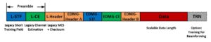
Preamble
Short Training Field, is STF used for receiver Automatic Gain Control, AGC, and synchronization, Automatic Frequency Control, AFC, whereas, Channel Estimation, CE is used for receiver assessment and adjustment of parametric depending on the channel behavior. Overall that is the purpose of “Preamble”, STF and CE.
Header
The Header is different for various PHY. It contains Modulation Coding Scheme, MCS, and the length of data, aka Checksum.
Data
Data is function of modulation and coding, MCS, and the length can vary depending on the PHY.
TRN
This an optional field meant for beamforming. It allows the beamforming algorithm to be trained and optimized via the User Equipment, UE, and/or Customer Premise Equipment, CPE.
Partner with ORTENGA to design and develop your new WiGig/802.11ad product.
5G mmW or WiFi 7
5G mmW wide bandwidth targets datarate up to 10bps with low latency.
The bandwidth is one of the key enablers plus better spectral efficiency based on Shannon limit.
As the frequency is increased into mmW band, the atmospheric loss, AL matters and pronounced in the radio range.
The following is AL in GHz spectrum range published by FCC, Bulletin Number 70, in July 1997.
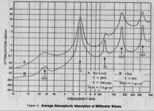
Therefore, when designing wireless connectivity from end user experience, the datarate (BW) and range are key parametric indicators to address for given EIRP.
WiFi 7 new 6 GHz band is also become player for delivery of high datarate due its wide bandwidth.
Regarding concert or sport arena wireless connectivity use case, WiFi 7 now competes and challenge 5G mmW service.
ORTENGA has seasoned engineering from Autonomous Automotive, SATCOM, radar, Smart City, WiFi, and Mobile Terrestrial Radio Communications System industries in Antenna, ASIC, Algorithm, HW, FW, and SW engineering disciplines.
WiGig 802.11ad Data Rate vs. Range
WiGig 802.11ad Data Rate vs. Range
The following graph illustrates Data Rate vs. Range for 802.11ad, aka WiGig, for OFDM signaling and Line of Sight, LOS, for mmW back haul applications.
The mmW back haul can be realized with HGBF architecture.
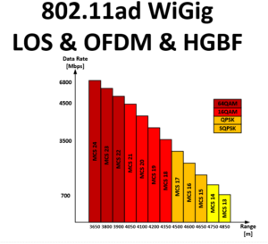
It takes into account the Atmospheric and path loss.
The system can be realized with Holograhpic Beamforming Architecture, HGBF.
ORTENGA has seasoned engineering from Autonomous Automotive, SATCOM, radar, Smart City, WiFi, and Mobile Terrestrial Radio Communications System industries in Antenna, ASIC, Algorithm, HW, FW, and SW engineering disciplines.
Digital Data Packet Quality of Service, QoS
Digital Data Packet Quality of Service, QoS should be application dependent.
For audio signal, e.g., phone call, human ears cannot distinguish better than 1 bit error in 1000 bits, i.e., BER = 1e-3.
Therefore, the QoS for audio call is BER ≤ 1e-3.
For visual signal, e.g., TV movie or picture human eyes have much higher resolution, 1 bit error in 1000,000,000, i.e., BER = 1e-9.
Therefore, the QoS for TV picture is BER ≤ 1e-9.
Combining these observations with Water Fall Curves, they reveal that as the BER decreases required Eb/N0 increases.
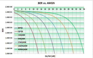
The Water Fall Curves reveal that as the spectral efficiency increase the required Eb/N0 is also increases, for given QoS which depends on the application.
ORTENGA has seasoned engineering from Autonomous Automotive, SATCOM, radar, Smart City, WiFi, and Mobile Terrestrial Radio Communications System industries in Antenna, ASIC, Algorithm, HW, FW, and SW engineering disciplines.
Partner with ORTENGA to define and develop your new product.
Digital Signal Detection
Analog signal and digital signal have different signal detection threshold.
Digital signal detection threshold is lower than analog signal detection.
While analog signal detection has a gray performance, digital signal detection is binary.
Technically, regardless of analog or digital a signal is detected when the signal is above the detection amplitude threshold.
Anything below the detection threshold amplitude is considered noise and ignored, while anything above the detection threshold amplitude is considered the signal of interest.
Therefore, the detection threshold differentiates signal from noise.
The detection threshold could be absolute in amplitude or relative to noise floor of the receiver via SINR or SNR.
The SINR or SNR is predetermined and programmed into the receiver FW.
Unlike communication signals where the receivers have error corrections capabilities due to redundancy, in radar applications there is no error correction, therefore there is a small chance of false alarm, i.e., appearance of target detection due to noise yet there is no actual target.
Consequently, signal detection threshold applies to radar signal for given false alarm rate.
ORTENGA helps businesses to identify required technical features to realize their business goals.
Partner ORTENGA in your next product concept, design, and development to realize that business goal.
ORTENGA has seasoned engineering from Autonomous Automotive, SATCOM, radar, Smart City, WiFi, and Mobile Terrestrial Radio Communications industries in Antenna, ASIC, HW, FW, and SW engineering disciplines.
Rayleigh vs. Rician Fading
Terrestrial Radio Link analysis consists of Line of Sight, Large Scale fading, Small Scale fading depending on the frequency, and Atmospheric Loss.
Large Scale Fading
Large scale fading refers to environment where the radio signal bounces of objects that are “much larger” than operating wavelength.
Large Scale fading is deterministic and it’s part of the Radio Link Budget Analysis.
Small Scale Fading
Small scale fading refers to fading environment where the radio signal bounces of objects that are “smaller” than operating wavelength.
Small Scale fading is random in nature, yet it can be introduced in the Radio Link Budget via Fade Margin. The fade margin represents the level of robustness for the Radio Link.
Small scale fading is typically modeled either by Rayleigh or Rician probability distribution function profile.
The radio signal is modulated by fading profile.
Rayleigh model reflects a channel with many multipath between transmitter and receiver which occurs in many Terrestrial radio applications, such as Cellular, i.e. 4G/5G, and WiFi, i.e. 802.11.
The probability distribution function describes the probability of occurrence as a function of radio signal envelope. The larger number of multipath between the transmitter and the receiver, the more spread the envelope radio signal envelope profile.
Rician model reflects a channel with one dominant, aka specular, path between the transmitter and the receiver. Obviously, the radio signal envelope for dominant path occurs with higher or distinct probability with respect to other multipath.
Rician model approaches Rayleigh probability density function as the dominant path becomes less and less in reflecting signal strength, therefore less pronounced.
In the case of 5G and WiFi applications, appropriate large and small scale fading terms must be included in the Radio Link Budget for robust radio design.
Partner with ORTENGA to analyze the Link Budget for your radio application and down select vendor/component for the design of new project.
MIMO OFDM Systems Architecture
MIMO and OFDM are two essential technologies for many radio systems communication new applications, such as 5G and WiGig/802.11ad.
The following diagram illustrates MIMO OFDM Systems Architecture for Tx and Rx, bits to bits.

The number of antennas can be scaled up to meet desired performance, power, size, weight, and cost requirements.
Partner with ORTENGA for design and development of your new wireless product from concept to production.