-
The Road to 5G and Beyond
- 5G Spectrum Allocations
- MIMO vs. Beamforming
- Digital Data Packet Quality of Service, QoS
- Signal Modulation
- Digital Signal Detection
- What is Matched Filter and why it is used?
- Rayleigh vs. Rician Fading
- MIMO OFDM Systems Architecture
- 5G Concatenated Coding Architecture
- Forward Error Correction, FEC
gNB is 5G Base Station with 3GPP New Radio, NR architecture.
The need for more capacity as well as reducing the CAPEX and OPEX cost of carrier operators have evolved to sets of new mobile wireless connectivity business requirements which effectively become 5G Technology.
5G Spectrum Allocations
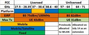
On July 14, 2016 FCC allocated 4 frequency bands above 24GHz to be used for 5G/next generation of wireless communication technology.
Here is snap shot of FCC ruling based on related documents.


Qualcomm, Ericsson, Verizon, Nokia, Samsung, XO, Straight Path, CTIA, TIA, Fiber Tower, and Intel’s representatives requested greater than 62dBm/100MHz EIRP level which was apparently accepted by FCC.
Now that we have FCC ruling behind us, 5G technology design, development, and deployment would gear into higher speed by industry to meet at 2020 Tokyo Summer Olympic. This is generating larger momentum for new opportunities in high tech industry, especially in U.S.
ORTENGA helps businesses to identify required technical features to realize their business goals.
MIMO vs. Beamforming
MIMO is based on multiple antennas similar to antenna array however each antenna is working independently of other antennas.
The overall data is decomposed to lower data rate and each antenna is transmitting portion of that data, independently.
In essence MIMO is using spatial diversity and multiplexing for very high data rate transmission. The spacing between each antenna is a wavelength to create adequate isolation while uncorrelated signals are picked up by each antenna.
Beamforming is achieved via Phased Array Antennas.
The Phased Array Antennas are based on array technologies which have been used extensively in military applications in the past 4 decades.
The antenna arrays electronically steers the beam to illuminate the intended target.
The beam steering occurs via changing the relative phase of each antenna element, such that the overall beam is formed of construction of Electromagnetic Waves at desired direction in the far field and produce higher SNR compare to single antenna at the receiver end.
The Phased Array Antennas are working together to achieve high gain/directional antenna, hence higher SNR at the receiver. The spacing between each antenna element is typically half wavelength to avoid grating lobe.
5G Technology will be utilizing massive MIMO as well as Beamforming, BF. Massive MIMO is intended for below 6GHz, whereas BF will be used for mmW bands (i.e. where wavelength is in order of mm, e.g. 30GHz).
ORTENGA helps businesses to identify required technical features to realize their business goals.
Digital Data Packet Quality of Service, QoS
Digital Data Packet Quality of Service, QoS should be application dependent.
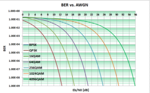
For audio signal, e.g., phone call, human ears cannot distinguish better than 1 bit error in 1000 bits, i.e., BER = 1e-3.
Therefore, the QoS for audio call is BER ≤ 1e-3.
For visual signal, e.g., TV movie or picture human eyes have much higher resolution, 1 bit error in 1000,000,000, i.e., BER = 1e-9.
Therefore, the QoS for TV picture is BER ≤ 1e-9.
Combining these observations with Water Fall Curves, they reveal that as the BER decreases required Eb/N0 increases.

The Water Fall Curves reveal that as the spectral efficiency increase the required Eb/N0 is also increases, for given QoS which depends on the application.
ORTENGA has seasoned engineering from Autonomous Automotive, SATCOM, radar, Smart City, WiFi, and Mobile Terrestrial Radio Communications System industries in Antenna, ASIC, Algorithm, HW, FW, and SW engineering disciplines.
Partner with ORTENGA to define and develop your new product.
Signal Modulation
In radio communication, the signal of interest is typically not at the radio frequencies.
In general radio frequencies, RF refers to frequencies at which a realizable size antenna can be utilized to covert electrons to photons, hence radio wave propagations. Therefore, there are at least two frequencies, one of the signals the other of the carrier, RF. The carrier is meant as the means to propagates between transmit to receive antennas. The method in which the signals of interest alter the carrier frequency, RF, is called modulation.
Here are some legacy modulation techniques which everyone uses in their daily life.
Amplitude Modulation, aka AM used in your car AM radio. The signals of interest alter the carrier amplitude, i.e. the amplitude of the carrier is the information which is meant for the receiver. This legacy modulation technique is susceptible to multipath fading. As you drive under a highway bridge, you notice that the AM radio audio signal is momentarily lost and comes back. This phenomenon is caused by multiple bounces of radio signal waves against the bridge and reaching your car radio. These radio waves sometime cancel each other and other time add constructively. The radio wave cancellation is fading of the signals of interest.
Frequency Modulation, aka FM used in your car FM radio to address multipath fading. While you are listening to FM radio under the highway bridge, you would not experience any loss of signal.
The above modulations are analog method of modulation. Nowadays, there more advance digital modulations. Digital modulations have three advantages over analog modulation.
- Spectrally more efficient over analog counter part
- More immune to noise, i.e. requires lower SNR for signal detections and discern
- More secure, as digital code changed between the transmitter and receiver
For the above reasons, digital modulations are ubiquitous.
Binary Phase Shift Keying, aka BPSK is the most basic digital modulation. The signals of interest are binary and embedded in the phase, 0 vs. 180 degrees of the carrier.
Quadrature Phase Shift Keying, aka QPSK is another digital modulation. The signals of interest are 2 bits and embedded as 45, 135, 225, 315 degrees phase of the carrier.
The binary codes are digital alphabet of modulation language.
It turns out the as the number of alphabets, bits increased, the more information can be encoded in the carrier, i.e. more spectrally efficient, bps/Hz.
On the other hand, as the number of alphabets, bits increased, additional signal to noise, SNR is required. In other words, the signals of interest are less immune to noise, consequently, additional power is required.
This is a challenge that communication engineering needs to balance, the trade off between spectral vs. power efficiency, hence digital modulation scheme design.
Work with ORTENGA to design your product.
Digital Signal Detection
Analog signal and digital signal have different signal detection threshold.
Digital signal detection threshold is lower than analog signal detection.
While analog signal detection has a gray performance, digital signal detection is binary.
Technically, regardless of analog or digital a signal is detected when the signal is above the detection amplitude threshold.
Anything below the detection threshold amplitude is considered noise and ignored, while anything above the detection threshold amplitude is considered the signal of interest.
Therefore, the detection threshold differentiates signal from noise.
The detection threshold could be absolute in amplitude or relative to noise floor of the receiver via SINR or SNR.
The SINR or SNR is predetermined and programmed into the receiver FW.
Unlike communication signals where the receivers have error corrections capabilities due to redundancy, in radar applications there is no error correction, therefore there is a small chance of false alarm, i.e., appearance of target detection due to noise yet there is no actual target.
Consequently, signal detection threshold applies to radar signal for given false alarm rate.
ORTENGA helps businesses to identify required technical features to realize their business goals.
Partner ORTENGA in your next product concept, design, and development to realize that business goal.
ORTENGA has seasoned engineering from Autonomous Automotive, SATCOM, radar, Smart City, WiFi, and Mobile Terrestrial Radio Communications industries in Antenna, ASIC, HW, FW, and SW engineering disciplines.
What is Matched Filter and why it is used?
Matched filter is the transfer function of the impulse response of the receiver.
Matched filter is utilized in both radio communication or radar systems DSP to maximize the SNR.
In radio communication systems, the matched filter is shifted time inversed pilot (known signal by transmitter and receiver) signal.
In radar systems, the matched filter is shifted time inversed transmitted waveform.
By convolving the incoming signals with its original waveform, maximum SNR can be achieved for DSP, consequently enhancing data extractions from the incoming signals.
Once again, radio communications and radar systems show their relevance and similarity with albeit different linguistic.
ORTENGA helps businesses to identify required technical features to realize their business goals.
ORTENGA is comprised of seasoned and skillful engineers who collaborate on innovative design in entrepreneurial environment to accomplish clients’ project.
Partner ORTENGA in your next product concept, design, and development to realize that business goal.
ORTENGA has seasoned engineering from Autonomous Automotive, SATCOM, radar, Smart City, WiFi, and Mobile Terrestrial Radio Communications industries in Antenna, ASIC, HW, FW, and SW engineering disciplines.
Rayleigh vs. Rician Fading
Terrestrial Radio Link analysis consists of Line of Sight, Large Scale fading, Small Scale fading depending on the frequency, and Atmospheric Loss.
Large Scale Fading
Large scale fading refers to environment where the radio signal bounces of objects that are “much larger” than operating wavelength.
Large Scale fading is deterministic and it’s part of the Radio Link Budget Analysis.
Small Scale Fading
Small scale fading refers to fading environment where the radio signal bounces of objects that are “smaller” than operating wavelength.
Small Scale fading is random in nature, yet it can be introduced in the Radio Link Budget via Fade Margin. The fade margin represents the level of robustness for the Radio Link.
Small scale fading is typically modeled either by Rayleigh or Rician probability distribution function profile.
The radio signal is modulated by fading profile.
Rayleigh model reflects a channel with many multipath between transmitter and receiver which occurs in many Terrestrial radio applications, such as Cellular, i.e. 4G/5G, and WiFi, i.e. 802.11.
The probability distribution function describes the probability of occurrence as a function of radio signal envelope. The larger number of multipath between the transmitter and the receiver, the more spread the envelope radio signal envelope profile.
Rician model reflects a channel with one dominant, aka specular, path between the transmitter and the receiver. Obviously, the radio signal envelope for dominant path occurs with higher or distinct probability with respect to other multipath.
Rician model approaches Rayleigh probability density function as the dominant path becomes less and less in reflecting signal strength, therefore less pronounced.
In the case of 5G and WiFi applications, appropriate large and small scale fading terms must be included in the Radio Link Budget for robust radio design.
Partner with ORTENGA to analyze the Link Budget for your radio application and down select vendor/component for the design of new project.
MIMO OFDM Systems Architecture
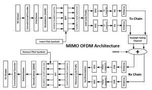
MIMO and OFDM are two essential technologies for many radio systems communication new applications, such as 5G and WiGig/802.11ad.
The following diagram illustrates MIMO OFDM Systems Architecture for Tx and Rx, bits to bits.

The number of antennas can be scaled up to meet desired performance, power, size, weight, and cost requirements.
Partner with ORTENGA for design and development of your new wireless product from concept to production.
5G Concatenated Coding Architecture
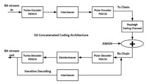
It is well known that by adding coding, error correction of digital signal enhances the radio communication performance by reducing the required transmit power for given BER, i.e. QoS, and/or increasing the range.
The tradeoff is in Latency as well as receiver decoder complexity and its implementation in the SoC.
5G is utilizing concatenated coding architecture in which 2 layers of known coding are providing enhanced error corrections with known decoding algorithms.
The following diagram illustrates 5G NR concatenated coding architecture used in UE.

Partner with ORTENGA in design and development of your radio communication systems.
Forward Error Correction, FEC
Advance messaging in radio communication systems have Forward Error Correction, FEC capability to enhance the reliability.
FEC allows the receiver first to become aware of errors, second to have ability in correcting the error.
Knowing the existence of any error in the received message is significant achievement, as it triggers additional investigation to rectify the message.
Depending on the FEC sophistications, the errors could be corrected.
3GPP 4G or 5G, WiFi, ATSC, SATCOM, DOCSIS standards have error correction capabilities.
Partner with ORTENGA to design and develop your new product.